Ultrasonic driving apparatus
a driving apparatus and ultrasonic technology, applied in electrical devices, piezoelectric/electrostrictive/magnetostrictive devices, piezoelectric/electrostriction/magnetostriction machines, etc., can solve the problems of deteriorating positioning precision, difficult to improve positioning precision, and deteriorating ultrasonic motor performance. achieve the effect of high degree of positional accuracy
- Summary
- Abstract
- Description
- Claims
- Application Information
AI Technical Summary
Benefits of technology
Problems solved by technology
Method used
Image

Examples
first embodiment
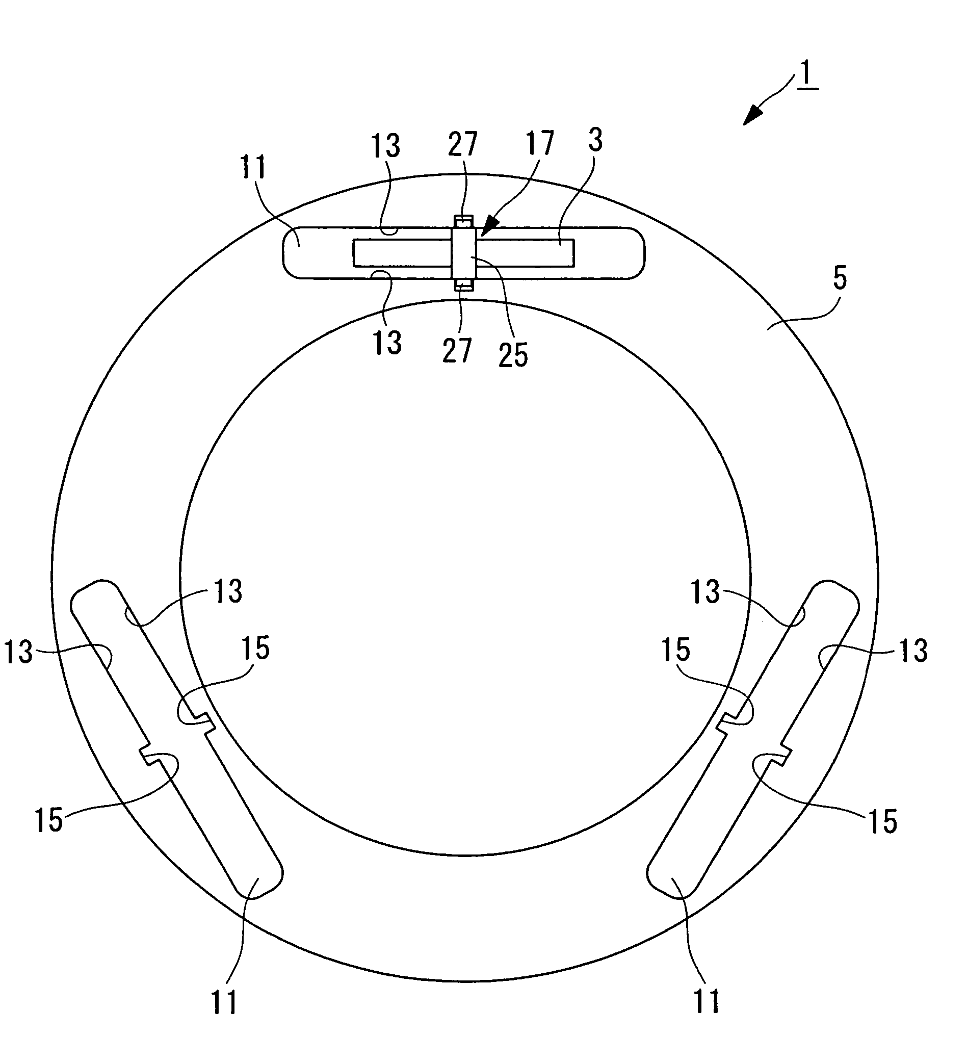
[0055]An ultrasonic driving apparatus according to a first embodiment of the present invention will be described below with reference to FIGS. 1 to 5. This embodiment is described in terms of an example in which the ultrasonic driving apparatus is used as an ultrasonic motor for driving a lens in a camera.
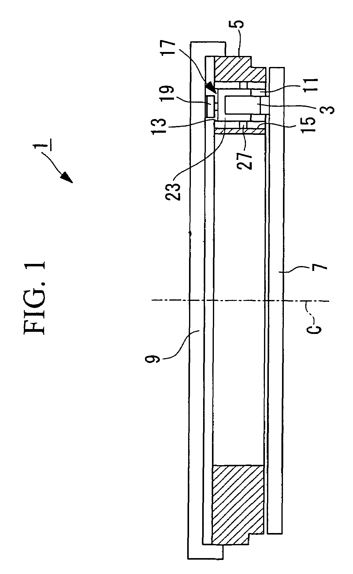
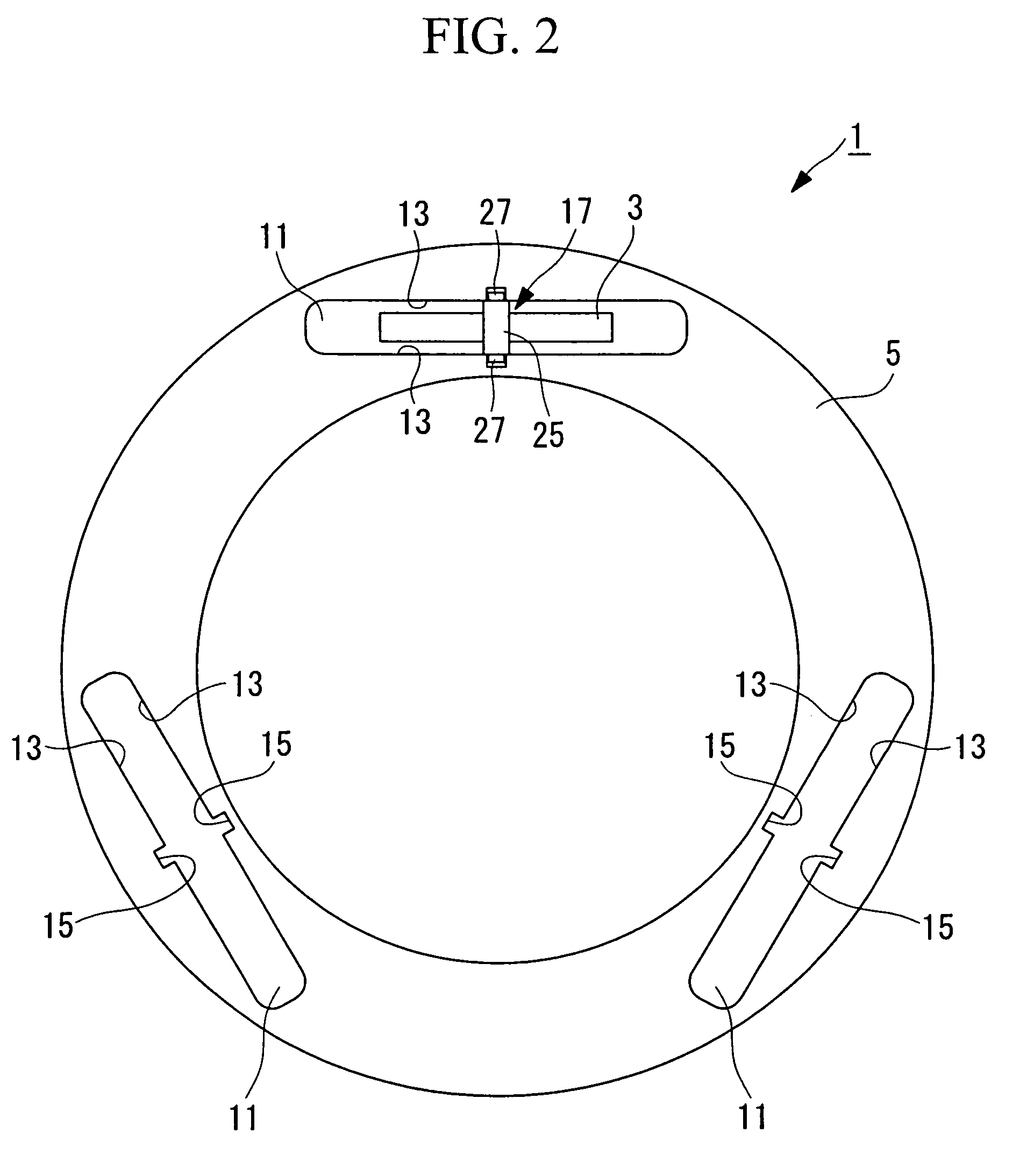
[0056]FIG. 1 is a cross-sectional view depicting the overall configuration of an ultrasonic motor according to the present embodiment. FIG. 2 is a partial plan view depicting the configuration of the ultrasonic motor in FIG. 1.
[0057]As shown in FIGS. 1 and 2, an ultrasonic motor (ultrasonic driving apparatus) 1 is mainly formed of a piezoelectric device (oscillator) 3 that produces ultrasonic vibrations when supplied with electrical power, a case (support member) 5 in which the piezoelectric device 3 is contained, a driven body 7 that is vibrated by the ultrasonic vibrations from the piezoelectric device 3, and a cover 9 for pressing the piezoelectric device 3.
[0058]A conversion me...
second embodiment
[0084]Next, a second embodiment of the present invention will be described with reference to FIGS. 6 and 7.
[0085]The basic configuration of the ultrasonic motor according to this embodiment is the same as that of the first embodiment described above, but the configuration of a holding part is different from that in the first embodiment. Therefore, in this embodiment, only the holding part shall be described using FIGS. 6 and 7, and the description of a cover and other elements will be omitted.
[0086]FIG. 6 is a plan view depicting the configuration of the ultrasonic motor according to this embodiment. FIGS. 7A and 7B are diagrams depicting a piezoelectric device in FIG. 6, wherein FIG. 7A shows the piezoelectric device as viewed from the radial direction of the ultrasonic motor, and FIG. 7B shows the piezoelectric device as viewed from the circumferential direction thereof.
[0087]The same reference numerals are assigned to the same constituent elements as in the first embodiment, and ...
third embodiment
[0095]Next, a third embodiment of the present invention will be described with reference to FIGS. 8 and 9.
[0096]The basic configuration of the ultrasonic motor of this embodiment is the same as that of the first embodiment described above, but the configuration of a holding part is different from that in the first embodiment. Therefore, in the present embodiment, only the holding part will be described using FIGS. 8 and 9, and a description of a cover and other elements will be omitted.
[0097]FIG. 8 is a plan view depicting the ultrasonic motor according to the present invention. FIGS. 9A and 9B are diagrams depicting the configuration of a piezoelectric device in FIG. 8, wherein FIG. 9A shows the piezoelectric device as viewed from the radial direction of the ultrasonic motor and FIG. 9B shows the piezoelectric device as viewed from the circumferential direction.
[0098]The same reference numerals are assigned to the same constituent elements as in the first embodiment and a descripti...
PUM
 Abstract
Description
Claims
Application Information
 - R&D
- Intellectual Property
- Life Sciences
- Materials
- Tech Scout
- Unparalleled Data Quality
- Higher Quality Content
- 60% Fewer Hallucinations
Browse by: Latest US Patents, China's latest patents, Technical Efficacy Thesaurus, Application Domain, Technology Topic, Popular Technical Reports.
© 2025 PatSnap. All rights reserved.Legal|Privacy policy|Modern Slavery Act Transparency Statement|Sitemap|About US| Contact US: help@patsnap.com