
Remote camouflage keypad for alarm control panel

Active Publication Date: 2008-09-16
BRITTON RICK A
View PDF22 Cites 13 Cited by
  • Summary
  • Abstract
  • Description
  • Claims
  • Application Information

AI Technical Summary

Benefits of technology

[0008]Conventionally, keypads have been mounted next to doors that are protected, or elsewhere which is as close as possible to afford a pedestrian authorized party convenient walk-up access to enter codes or the like to disable within a given grace time an alarm event. To date such keypads are very visible. Even if the codes to disabling delayed-alarm events within the grace period are generally held secrets among a small set of authorized parties, the problem is that such keypads' key arrangement is permanently visible to non-authorized parties. Hence, a non-authorized observer observing an authorized user entering a code from afar might be able to discern the authorized party's finger stroke and hence stealthily deduce the code. For instance, a code of “6985” on a standard keypad is accomplished through a simple square of keystrokes on a standard keypad. Such a code is easily discerned from a far back vantage point.

Problems solved by technology

However, in the industry it is called “control panel,” perhaps because in earlier years all the necessary circuitry and devices could be contained in something the size more readily describable as a “panel.” Nowadays, however, such circuitry and devices are contained in a rather bulky cabinet, which is typically hidden out of sight in a closet or the like.
Instead, the actual end-use customers (or let's say a relatively small set of authorized employees or parties thereof) are relatively limited as to what control instructions they can enter to their local premise-monitoring alarm control panel, and inter alia physically by way of a keypad.
Even if the codes to disabling delayed-alarm events within the grace period are generally held secrets among a small set of authorized parties, the problem is that such keypads' key arrangement is permanently visible to non-authorized parties.
That way, a distant observer observing a geometric pattern of finger strokes cannot simply deduce the code from common knowledge of a conventional keypad arrangement.

Method used


Image

  • Remote camouflage keypad for alarm control panel
  • Remote camouflage keypad for alarm control panel
  • Remote camouflage keypad for alarm control panel

Examples


Embodiment Construction

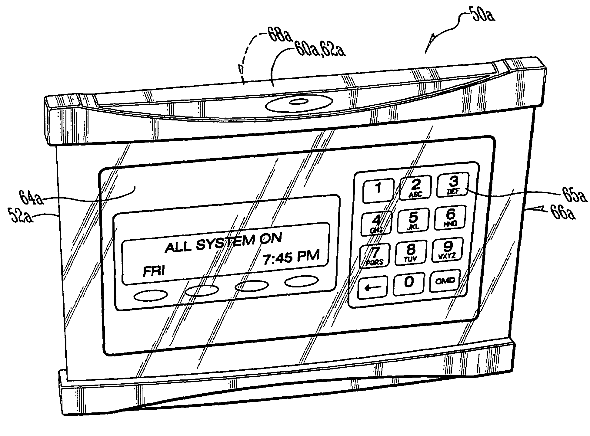
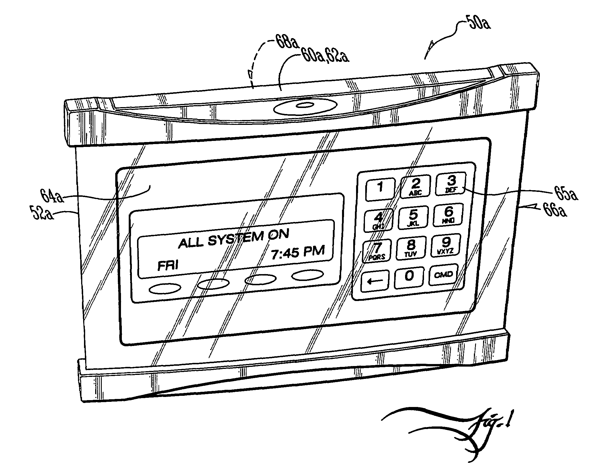
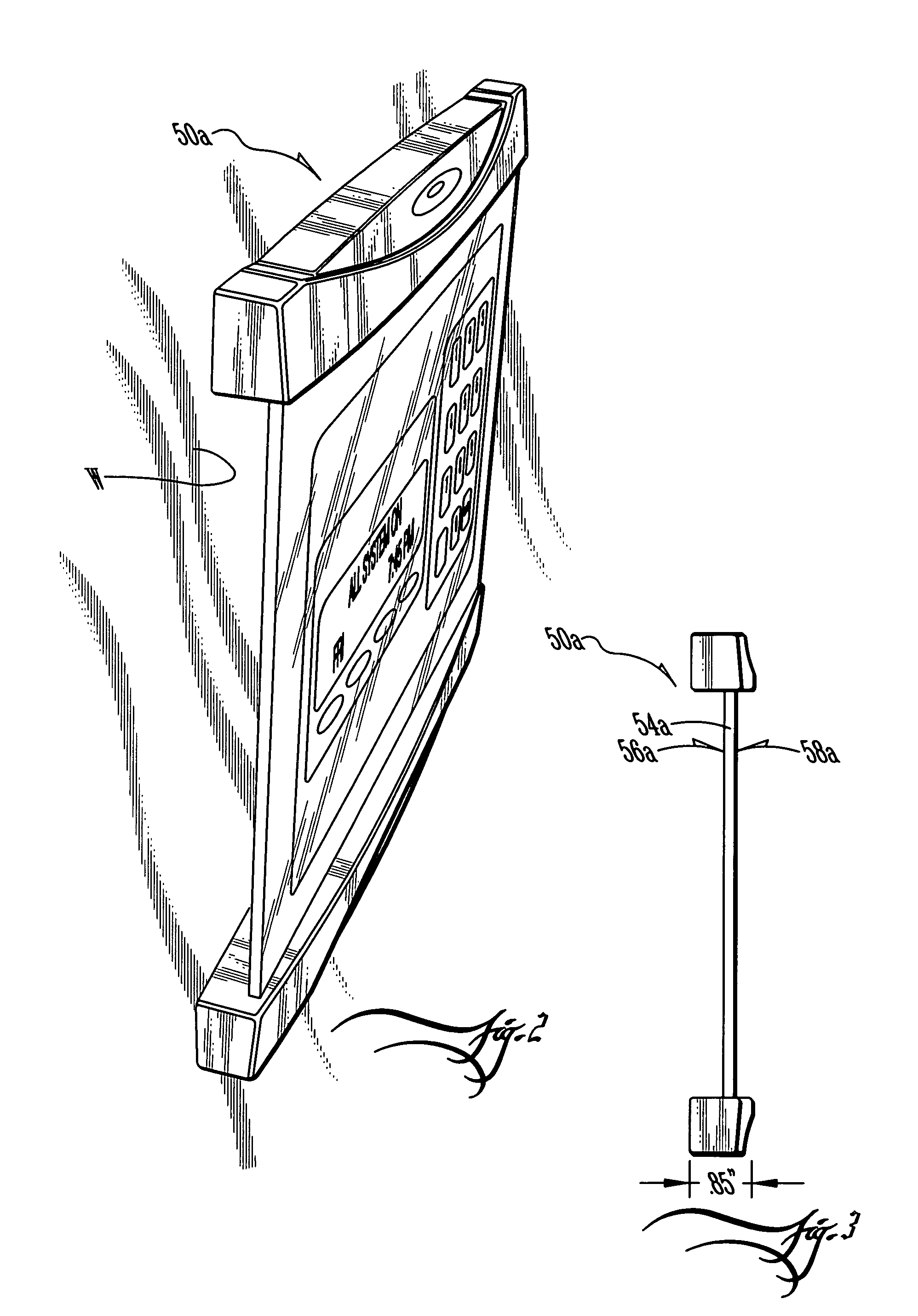
[0033]FIGS. 1-4 comprise a set showing a first preferred embodiment 50a for the invention, FIGS. 5-8 comprise a set showing a second preferred embodiment 50b for the invention, FIGS. 9-12 comprise a set showing a third preferred embodiment 50c for the invention, and FIGS. 13-16 comprise a set showing a fourth preferred embodiment 50d for the invention. For convenience in this written description, wherever a reference numeral is used herein (eg., “50”) that has comparable counterparts on any or all other versions, on the drawing itself the reference numeral will be affixed with an alphabet-letter post-fix for distinguishment purposes:—wherein postfix letter “a” will be utilized in FIGS. 1-4 for the first preferred embodiment 50a, postfix letter “b” will be utilized in FIGS. 5-8 for the second preferred embodiment 50b, postfix letter “c” will be utilized in FIGS. 9-12 for the third preferred embodiment 50c and then, naturally enough, postfix letter “d” will be utilized in FIGS. 13-16 ...


PUM


Abstract

A glass keypad for an automatic premise-monitoring alarm system of remote sensors linked to a control panel has a screen defined by a peripheral edge spacing inboard and outboard faces and allowing a flush or closely gapped mounting to a wall. There is also operative circuitry and devices as well as a diminutive housing that conceals the circuitry and devices and is mounted to the peripheral edge and / or outboard face. Thus, the glass keypad has display mode, where a display is illuminated on the screen including illuminated keys for entry of inputs to the control panel, as well as a sleep mode in which the illumination is switched to reduced power such that the keypad display is invisible. The reduced power state is off or very low such that any color, texture or design on the wall shows through, the glass keypad thus self-camouflaging itself.

Description

CROSS-REFERENCE TO PROVISIONAL APPLICATION(S)[0001]This application claims the benefit of U.S. Provisional Application No. 60 / 495,281, filed Aug. 15, 2003.BACKGROUND AND SUMMARY OF THE INVENTION[0002]The invention relates to automatic, premise-monitoring alarm systems as for example burglary, otherwise unauthorized access and / or fire alarm systems, and more particularly to a remote camouflage keypad for user input to the local premise's alarm control panel, as will be apparent in connection with the discussion further below of preferred embodiments and examples.[0003]Premise-monitoring alarm systems monitor a given protected premise—say, for example, a residential home, a commercial property, a bank vault, access through a given door or throughway, or an ATM machine and the like—for the occurrence of a given alarm event:—e.g., an unwanted intrusion, unauthorized entry or smoke and so on. Some alarm events simply correspond to a “low battery” condition in either the alarm-event senso...

Claims


Application Information

Patent Timeline
IPC IPC(8): G09G5/00
CPCG06F1/3203G06F1/3262G08B25/14G06F3/04886G08B15/001G06F3/0412
Inventor BRITTON, RICK A.
Owner BRITTON RICK A
Learn More