
Optical repeater converting wavelength and bit rate between networks

a technology of optical repeaters and networks, applied in the field of repeaters, can solve problems such as difficulty in connecting optical networks with different signal wavelengths and bit rates together, and mismatch in signal velocity of different networks

Inactive Publication Date: 2008-09-09
FUJITSU LTD
View PDF22 Cites 2 Cited by
  • Summary
  • Abstract
  • Description
  • Claims
  • Application Information

AI Technical Summary

Benefits of technology

The present invention provides an optical repeater that can convert optical signals from one network to another with different wavelengths and bit rates. This is achieved by including a wavelength converter and a bit rate converter in the optical repeater. The optical repeater can transmit the converted optical signals to the second network at the converted bit rate and wavelength. The technical effect of this invention is to enable seamless connectivity and flexibility in optical networks.

Problems solved by technology

Therefore, there may be difficulties when connecting such optical networks having different signal wavelengths and bit rates together.
For example, when a signal of 10 Gb / s is directly connected to the optical network of 25 GHz channel space, a problem is generated in which the crosstalk to the adjacent channel is generated by the signal frequency width of the signal of 10 Gb / s.
When connecting optical networks of different signal bit rate, there may be a mismatch in the signal velocity of the different networks.

Method used


Image

  • Optical repeater converting wavelength and bit rate between networks
  • Optical repeater converting wavelength and bit rate between networks
  • Optical repeater converting wavelength and bit rate between networks

Examples


Embodiment Construction

[0048]Reference will now be made in detail to the present preferred embodiments of the present invention, examples of which are illustrated in the accompanying drawings, wherein like reference numerals refer to like elements throughout.

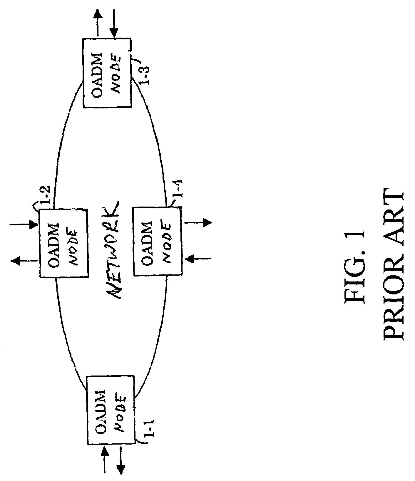
[0049]FIG. 3 is a diagram illustrating two networks connected together, according to an embodiment of the present invention. Referring now to FIG. 3, ring network A is formed by connecting OADMs 1-1, 1-2, 1-3 and 1-4 together through a transmission line consisting of an optical fiber. Similarly, ring network B is formed by connecting OADMs 1-5, 1-6, 1-7 and 1-8 together through a transmission line consisting of an optical fiber.

[0050]Network A and network B are different in the signal bit rate and signal channel space(wavelength interval). For example, in network A, the bit rate is 10 Gb / s, there are 32 channels with 100 GHz channel space. In network B, the bit rate is 2.5 Gb / s, there are 128 channels with 25 GHz channel space.

[0051]Network A and netw...


PUM


Abstract

An optical repeater which includes a wavelength converter and a bit rate converter. The wavelength converter converts a wavelength of an optical signal from a first optical network to a wavelength of a second optical network. The bit rate converter converts a bit rate of the optical signal from the first optical network to a bit rate of the second optical network. The optical repeater transmits the optical signal from the first optical network to the second optical network at the converted bit rate and wavelength.

Description

[0001]This application is a divisional of application Ser. No. 09 / 537,756, filed Mar. 30, 2000, now U.S. Pat. No. 6,810,215 now allowed.CROSS-REFERENCE TO RELATED APPLICATIONS[0002]This application is based on, and claims priority to, Japanese Application No. 11-201767, filed Jul. 15, 1999, in Japan, and which is incorporated herein by reference.BACKGROUND OF THE INVENTION[0003]1. Field of the Invention[0004]The present invention relates to a repeater for connecting individual networks which together form a larger photonics network utilizing optical wavelength division multiplexing (WDM). More particularly, the present invention relates to a repeater which transmits an optical signal from a first network to a second network, and converts a bit rate and wavelength of the optical signal to that suitable for the second network.[0005]2. Description of the Related Art[0006]Optical wavelength division multiplexing (WDM) transmission systems are now under development to dramatically increa...

Claims


Application Information

Patent Timeline
Patent Type & Authority Patents(United States)
IPC IPC(8): H04B10/02H04B10/27H04B10/2507H04B10/275H04B10/29H04B10/291H04J14/00H04J14/02H04L12/42H04L12/46
CPCH04B10/27H04B10/271H04J14/02H04B10/29H04B10/275
Inventor OIKAWA, YOICHI
Owner FUJITSU LTD
Learn More