
Method, apparatus and computer program product for injecting current

a technology of current injection and computer program, applied in the direction of electric generator control, dynamo-electric converter control, instruments, etc., can solve the problems of system controllability degradation, generator and other turbine components subjecting the generator and other turbine components to repeated transients, and limited negative sequence voltage, current or power supply ability of the system

Active Publication Date: 2008-09-09
GE INFRASTRUCTURE TECH INT LLC
View PDF55 Cites 105 Cited by
  • Summary
  • Abstract
  • Description
  • Claims
  • Application Information

AI Technical Summary

Benefits of technology

The patent describes a method, apparatus, and computer program for modifying the effect of disturbances in an electric grid on a generator connected to the grid. This is achieved by tracking the negative and positive sequence components of the grid signal, and then injecting a portion of the negative sequence component into the grid to modify the disturbance. The technical effect of this invention is to provide a means for reducing the impact of disturbances on generators, improving the stability and reliability of the electric grid.

Problems solved by technology

Remaining connected during system fault (often referred to as “low voltage ride through”) can be challenging from an engineering perspective.
Unfortunately, turbine systems may be limited in their ability to supply adequate negative sequence voltage, current or power.
This leads to degradation of system controllability, and repeated operation of protection measures (e.g., a “crowbar circuit”), thus subjecting the generator and other turbine components to repeated transients.
Unfortunately, traditional current management schemes typically impede techniques for coordinated protection of branch and feeder circuits.
Traditional solutions to address these challenges have resulted in systems with non-linear behaviors, making it difficult to provide simple models of sub-system elements for use in full-system models.
Design of experiments typically becomes quite complex, as exhaustive scenarios are needed to attempt to cover the locus of the non-linear system.
Typically, when using this approach, the power generation equipment is unable to respond properly in light of new standards and demands for generation systems.

Method used


Image

  • Method, apparatus and computer program product for injecting current
  • Method, apparatus and computer program product for injecting current
  • Method, apparatus and computer program product for injecting current

Examples


Embodiment Construction

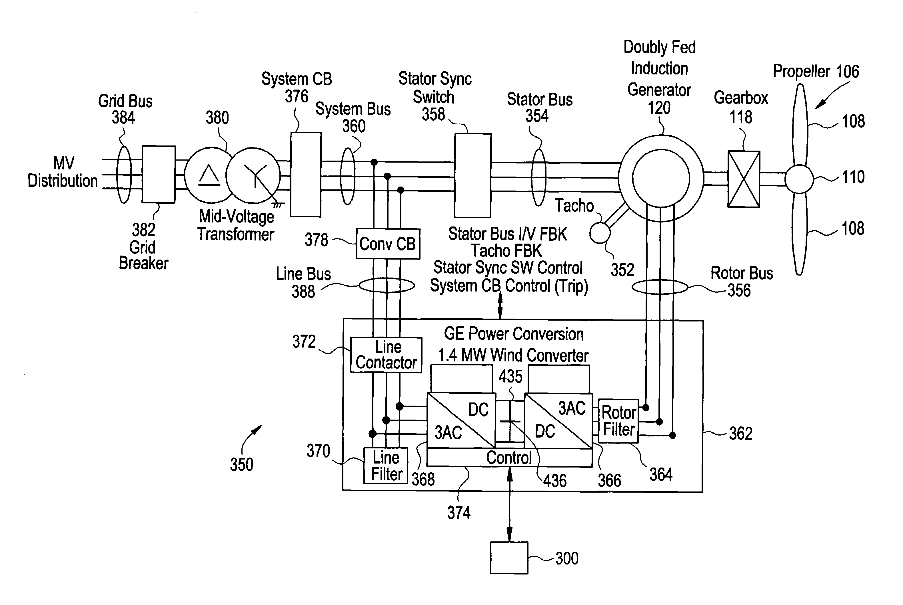
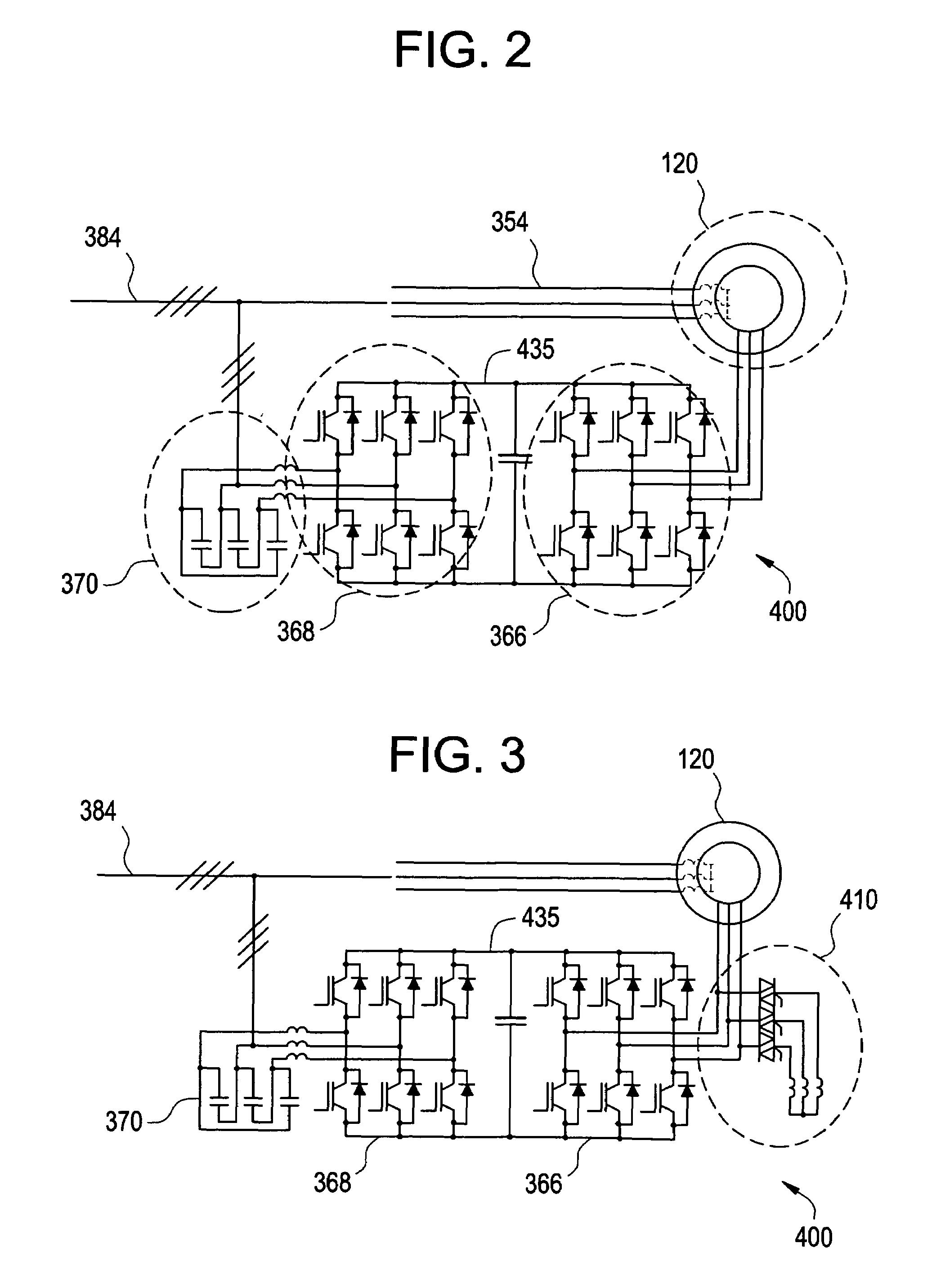
[0032]The teachings herein provide for determination of the levels of negative sequence voltage in a disturbance and, except for short transient crowbar circuit protections at initiation of the disturbance, a response that permits control of the positive and negative sequence currents flowing into the faulted condition. Limits on the positive and negative sequence current will depend on system parameters such as system conditions, system capability and topology of the converter equipment. The resultant control capability can be used to improve the response of the generator during asymmetric grid voltage conditions.

[0033]The teachings herein provide techniques for modifying the effects of a disturbance in an electric grid upon a generation asset (e.g., a wind turbine). The techniques for modifying the effect of the disturbance provide for maintaining a connection with the electric grid during a system fault, and providing appropriate behavior to the point of connection with the grid....


PUM


Abstract

Method and apparatus that provide a response to the negative sequence current demands during a disturbance of the grid system connected to power-generating equipment, such as a wind turbine system, provide for tracking components in the grid signal, orienting at least a portion of the signal, and injecting the oriented portion. Controlled injection of negative sequence current provides for extending small-signal control response, and also provides for modifications of the apparent impedance to the grid interconnect of the power conversion equipment.

Description

BACKGROUND OF THE INVENTION[0001]The teachings herein relate generally to techniques for rapid compensation of phase and amplitude information in an electrical signal.[0002]Many countries now require that wind turbines used as electric generation facilities stay connected with the electric grid when the grid is in fault. Remaining connected during system fault (often referred to as “low voltage ride through”) can be challenging from an engineering perspective. Perhaps most importantly, the phase and amplitude information of the sequence components in the grid signal must be made available to the turbine control systems quickly and accurately. This permits the control systems to make timely adjustments to the wind turbine, thereby mitigating the effect of any large signal transients and thus prevent tripping of the wind turbine.[0003]Generally, the primary goal of a power generation asset is to control positive sequence voltage. Traditional current regulated approaches implicitly att...

Claims


Application Information

Patent Timeline
Patent Type & Authority Patents(United States)
IPC IPC(8): H02H7/06F02N11/06H02P11/00H02P9/00H02P9/04
CPCF03D9/003H02P9/007H02P29/025H02J3/386H02P2101/15Y02E10/72Y02E10/763H02P2207/073F03D9/255H02J2300/28H02J3/381Y02E10/76H02J3/40
Inventor WENG, HAIQINGSEYMOUR, ROBERT A.D'ATRE, JOHN D.RITTER, ALLEN M.YUAN, XIAOMINGDAI, RENCHANGDELMERICO, ROBERT W.
Owner GE INFRASTRUCTURE TECH INT LLC
Learn More