
Illumination device

a technology of illumination device and illumination light, which is applied in the direction of lighting support device, color-music apparatus, application, etc., can solve the problems of not teaching about any construction for preventing internal parts, no illumination device to approximate illumination light, and difficult commercialization

Inactive Publication Date: 2008-09-09
YUUSU ENG
View PDF11 Cites 25 Cited by
  • Summary
  • Abstract
  • Description
  • Claims
  • Application Information

AI Technical Summary

Benefits of technology

[0009]It is also desirable to provide an illumination device capable of increasing, when projecting illumination light in a shape like a candle frame onto the surface of a shade member, the flaring of the illumination light like a candle frame.
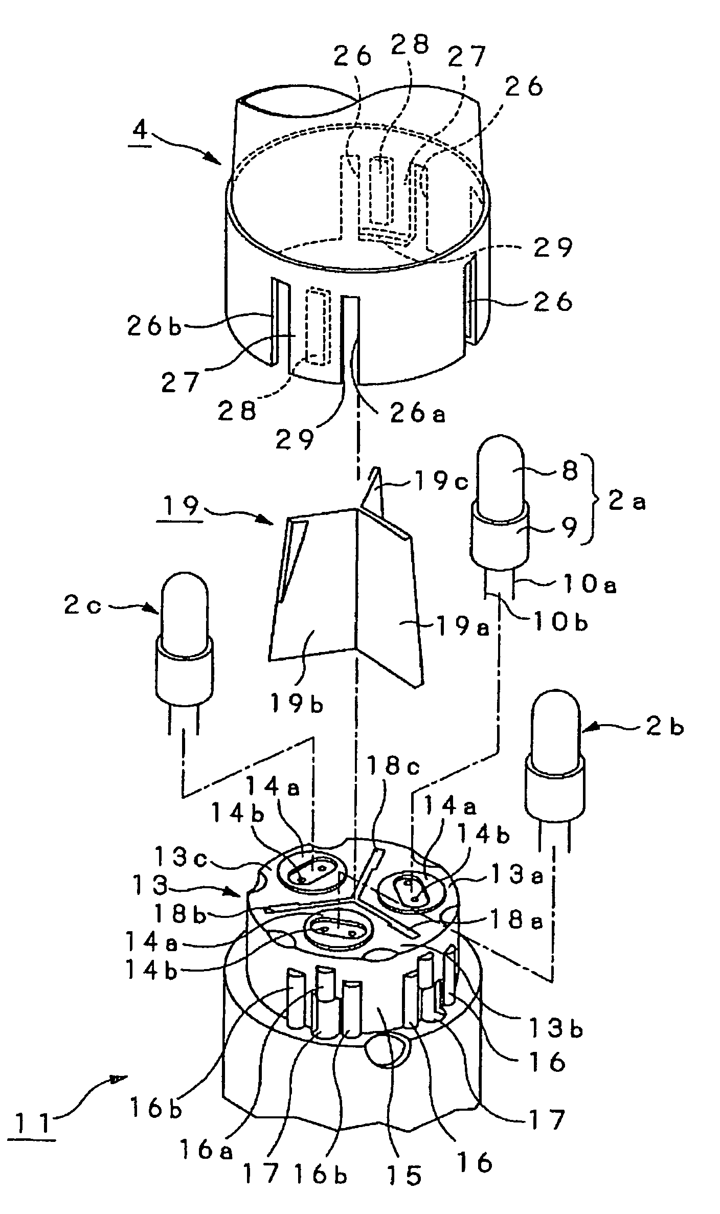
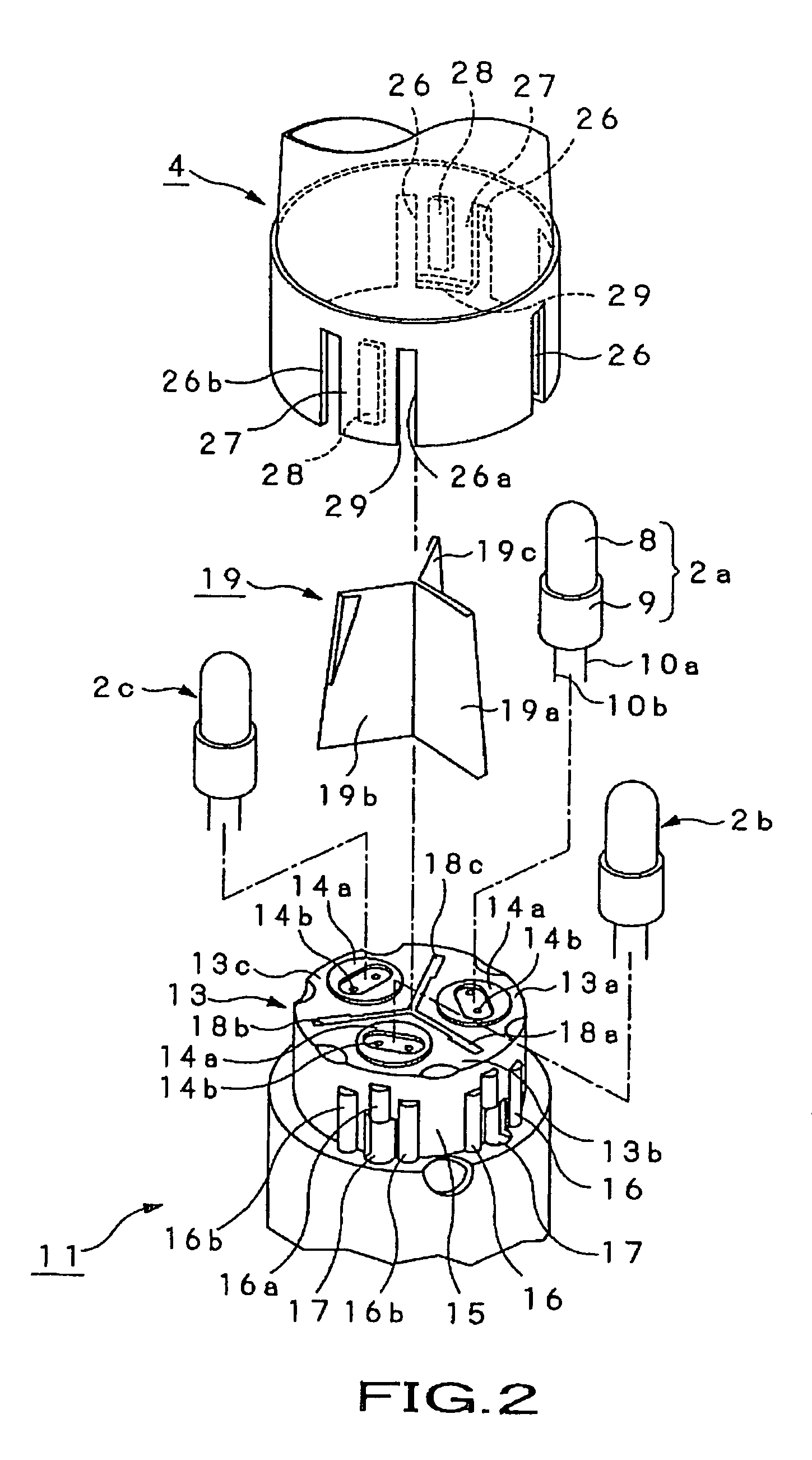
[0010]According to the present invention, there is provided an illumination device including a plurality of light sources changed in light emission individually by a control circuit, a lighting stand including a torch portion and base portion, light scattering member, shade member and shielding / diffusing member. In the lighting stand, the torch portion has installed integrally thereto a light source support to support each of the light sources at a predetermined height removably, and the base portion supports the torch portion in upright position. The light scattering member is formed from a cap-shaped member removably fitted to the light source support to scatter illumination light emitted from each light source. The shade member is shaped in the form of a transparent or semitransparent cylinder having a longer axis and larger diameter than the lighting stand, and installed to surround the lighting stand. The shade member has the outer surface thereof formed linearly in the axial direction, for example, to refract vertical light for vertical diffusion and thus for easy appearance of vertical flaring. The shielding / diffusing member is removably installed inside the shade member to shield the lighting stand while further diffusing the illumination light emitted from each light source and diffused by the light scattering member so that the illumination light will go out of the outer surface of the shade member. Having elasticity for radial spread-out from a rolled-up state, the shielding / diffusing member is in close contact with the inner surface of the shade member.
[0012]In the illumination device according to the present invention, since the shade member is formed cylindrical and the distance between the light scattering member and shade member is shorter than in the conventional illumination device, the light scattered by the light scattering member and projected on the shade member having the shielding / diffusing member provided on the inner surface thereof will easily appear to flare on the outer surface of the shade member. Especially, a shade member whose outer surface is axially straight will create remarkable vertical flaring of the illumination light, more approximate to a candle frame.

Problems solved by technology

However, the Patent Document 1 teaches nothing about any construction for preventing the internal parts such as the light sources, for example, from being directly visible from outside when the illumination device is in use.
Therefore, this illumination device has no function to approximate the illumination light to a candle frame which will create a healing or comforting atmosphere as in the Patent Documents 1 and 3.
The illumination device disclosed in the Patent Document 3 is not advantageous in that it needs the multiple light emitters that emit light of different color tones and are not easy to commercially obtain.
Thus, for illumination light with different color tones corresponding to places and atmospheres where the illumination device is used, the globe and light sources have to be replaced, which will be very troublesome.

Method used


Image

  • Illumination device
  • Illumination device
  • Illumination device

Examples


Embodiment Construction

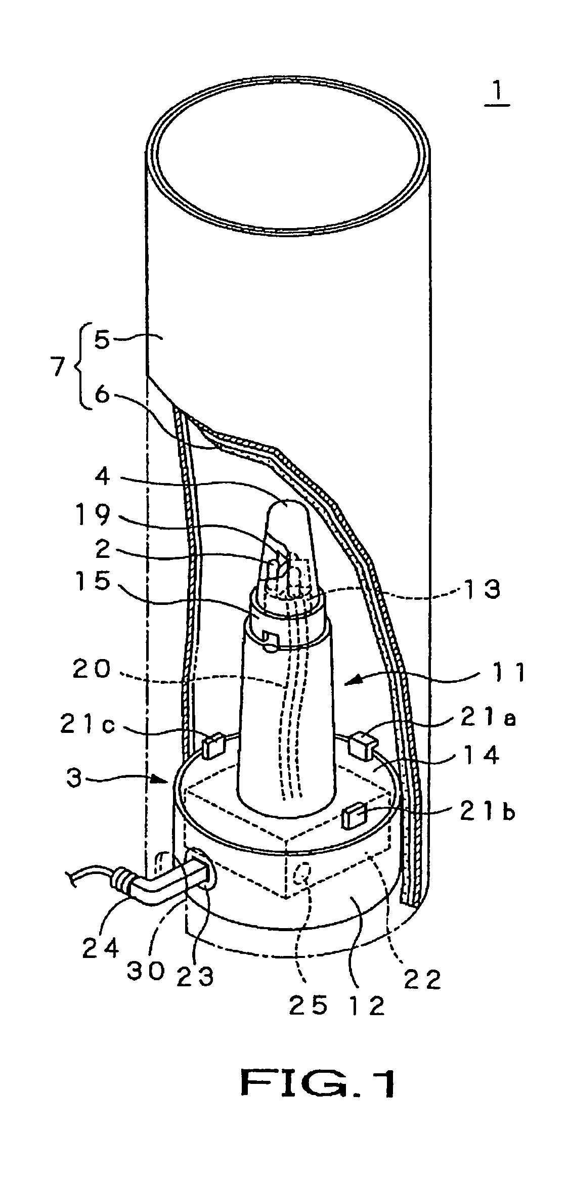
[0022]The present invention will be described in detail below concerning the embodiments of the present invention with reference to the accompanying drawings. FIG. 1 shows an illumination device, generally indicated with a reference numeral 1, as the first embodiment of the present invention.

[0023]The illumination device 1 is to be used on a table or the like in a relatively gloomy living room or restaurant. The illumination device 1 will create a healing or comforting atmosphere by providing an elongated, flaring illumination like a familiar candle flame.

[0024]As shown in FIG. 1, the illumination device as the embodiment of the present invention includes three light sources 2a to 2c, lighting stand 3 having the light sources 2a to 2c fixed thereto, light scattering member 4 to scatter light emitted from the light sources 2a to 2c fixed to the lighting stand 3, and a shade 7 composed of a shade member 5 disposed around the lighting stand 3 and a shielding / diffusing member 6 disposed...


PUM


Abstract

An illumination device is provided which includes a lighting stand (3) in which a torch portion (11) including a light source support (13) on which a plurality of light sources (2a to 2c) is supported is provided upright on a base in which a control circuit unit (22) to change the light emission from each of the light sources 2a to 2c, a light scattering member (4) formed by molding a semitransparent resin to have a cap-like shape nearly like a candle frame, fitted on the light source support (13) and which scatters the illumination light emitted from the light sources (2a to 2c), to be bright itself, a shade member (5) formed from a transparent resin and attached over the outer surface of the lighting stand (3), and a shielding / diffusing member (6) assembled, being rounded like a cylinder, inside the shade member (5) to diffuse the illumination light emitted from the light sources (2a to 2c). Thus, the illumination light emitted from the light sources can be projected on the shade member (5) to create flaring illumination light like a candle frame.

Description

TECHNICAL FIELD[0001]The present invention relates to an illumination device including a plurality of light sources each being an incandescent lamp and adapted to present light from the light sources as flaring illumination light which looks like a candle frame.[0002]This application claims the priority of the Japanese Patent Application No. 2003-342104 filed in the Japanese Patent Office on Sep. 30, 2003, the entirety of which is incorporated by reference herein.BACKGROUND ART[0003]The illumination device such as a candlestick functions to simply lighten a living space or the like as well as to create a healing or comforting atmosphere by indirect or controlled lighting. For example, the Japanese Patent Application Laid Open No. 106890 of 1997 (will be referred to as “Patent Document 1” hereunder) discloses an illumination device that includes a plurality of light sources disposed in different positions of one support and a controller that controls the light emission from the light...

Claims


Application Information

Patent Timeline
Patent Type & Authority Patents(United States)
IPC IPC(8): F21V7/04F21S10/04F21V17/06
CPCF21S6/001F21S6/004F21S10/04F21V1/00F21V1/12F21V9/08F21V23/04F21V5/00F21Y2101/02F21V17/06F21W2121/00F21Y2115/10
Inventor HIRATA, TOSHIMI
Owner YUUSU ENG
Learn More