
Fall detection device

a technology of falling detection and detection device, which is applied in the direction of hydrodynamic testing, acceleration measurement using interia force, instruments, etc., can solve the problems of lowering the reliability of fall detection, the difficulty of accurately detecting a fall, and information stored in a mobile device hard disk device, so as to reduce the size improve the reliability of the fall detection device, and prevent the effect of error due to other movements

Inactive Publication Date: 2008-08-19
LAPIS SEMICON CO LTD
View PDF3 Cites 5 Cited by
  • Summary
  • Abstract
  • Description
  • Claims
  • Application Information

AI Technical Summary

Benefits of technology

[0026]In the present invention, it is possible to determine the rotating fall state separated from other movements, so that an erroneous result due to other movements is prevented, thereby improving reliability of the fall detection device. Further, the fall determining device can be formed of a single three-axial acceleration sensor and a microcomputer, thereby decreasing a size of the fall detection device.

Problems solved by technology

When the acceleration component does not become below the threshold value, it is difficult to accurately detect a fall even though the object is actually falling.
Accordingly, information stored in a hard disk device in a mobile device may be damaged, thereby lowering reliability of fall detection.
Accordingly, it is necessary to provide a supply source of the alternate current signals and the voltage detection device in the fall detection device, thereby making a structure of the fall detection device complex and increasing a size of the fall detection device.
Accordingly, even though it is possible to detect an angular velocity and determine that the mobile device rotates, when it is erroneously determined that the mobile device is under a free fall state even though the mobile device rotates associated with the swing movement, a magnetic head is retracted too frequently.
As a result, power consumption increases, and it takes long time to read and write information from and in the hard disk, thereby decreasing a processing speed of the mobile device.

Method used


Image

  • Fall detection device
  • Fall detection device
  • Fall detection device

Examples


Embodiment Construction

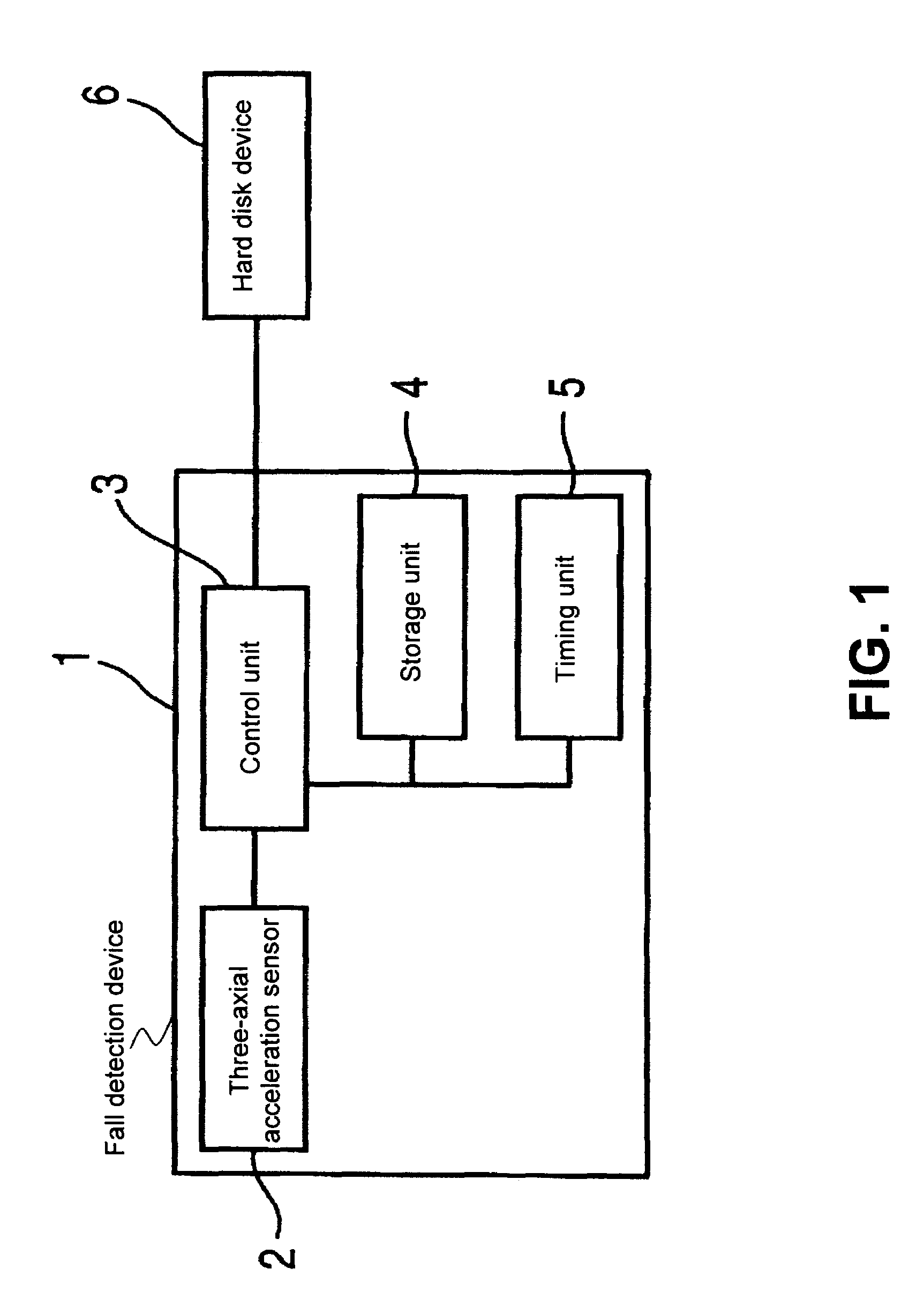
[0035]Hereunder, embodiments of the present invention will be explained with reference to the accompanying drawings. FIG. 1 is a block diagram showing a fall detection device 1 according to an embodiment of the present invention.

[0036]As shown in FIG. 1, the fall detection device 1 is provided with a three-axial acceleration sensor 2. The three-axial acceleration sensor 2 may include a weight portion, a flexible portion arranged along four directions of the weight portion in a cross shape, and a bridge circuit formed of piezo resistance elements and arranged on the flexible portion for converting deformation generated in the flexible portion to an electrical signal. Accordingly, the three-axial acceleration sensor 2 has a function of outputting acceleration components as acceleration component signals in three axes, i.e., an X-axis, a Y-axis, and a Z-axis, crossing perpendicularly with each other.

[0037]Further, the fall detection device 1 is provided with a control unit 3 such as a ...


PUM

PropertyMeasurementUnit
timeaaaaaaaaaa
heightaaaaaaaaaa
timeaaaaaaaaaa

Abstract

In a fall detection device, when a first composite vector value of a first acceleration component obtained from a three-axial acceleration sensor is greater than a rotating fall determining value, or smaller than a free fall determining value, a possibility of a fall is determined. When a second composite vector value of a second acceleration component obtained after a determining time interval is greater than the rotating fall determining value, and an angular difference of each testing surface is greater than an angular difference determining value, it is determined to be in the middle of a fall. Further, when a third composite vector value of a third acceleration component obtained one more time is smaller than the free fall determining value, it is determined to be in the middle of a fall.

Description

BACKGROUND OF THE INVENTION AND RELATED ART STATEMENT[0001]The present invention relates to a fall detection device with a three-axial acceleration sensor for detecting a fall.[0002]Recently, a dimension of a hard disk device has been reduced while a capacity thereof has been increased. Accordingly, various types of mobile devices such as a cellular phone are provided with hard disk devices. When a mobile device is provided with a hard disk device having relatively low impact resistance, it is necessary to protect information stored in the hard disk device from an impact of a fall, so that the information is prevented from being damaged. To this end, it has been tried to detect a fall of a mobile device, so that a magnetic head is retracted from a magnetic disk of a hard disk device.[0003]A conventional fall detection device is provided with a three-axial acceleration sensor for detecting acceleration components in three axes crossing perpendicularly with each other. When each of th...

Claims


Application Information

Patent Timeline
Patent Type & Authority Patents(United States)
IPC IPC(8): G06F19/00G01P15/18G11B21/12
CPCG01P15/0891G11B21/12G11B19/043G01P15/18
Inventor SUZUKI, TAKEHARU
Owner LAPIS SEMICON CO LTD
Learn More