
Reusable cartridge oil filter

a technology of oil filter and reusable cartridge, which is applied in the direction of moving filter element filter, filtration separation, and separation process, etc., can solve the problems of difficult disposal of used filters, less than ideal paper filtering, and substantial increase in the cost of oil filtering

Active Publication Date: 2008-08-19
HAMMOND ENTERPRISES INC
View PDF23 Cites 36 Cited by
  • Summary
  • Abstract
  • Description
  • Claims
  • Application Information

AI Technical Summary

Problems solved by technology

However, they also have certain disadvantages, since not only is the filter element (the paper filter) effectively replaced on each oil change, but the pressure container in which the filter element is mounted is also replaced on each oil change.
Consequently, the cost of these filters substantially increases the cost of the oil change itself.
Also, the filtering of the paper is less than ideal, the paper catching only a percentage of particles of a given size, with the paper clogging over time so that increasing percentages of the recirculating oil bypasses the filter entirely.
While filters of the foregoing type are easily removed from an engine and replaced with a new filter, the used filter is not easily disposed of.
Being toxic, the used filter cannot simply be thrown out, so to speak, as before, but rather must be disposed of using prescribed and relatively expensive procedures.

Method used


Image

  • Reusable cartridge oil filter
  • Reusable cartridge oil filter
  • Reusable cartridge oil filter

Examples


Embodiment Construction

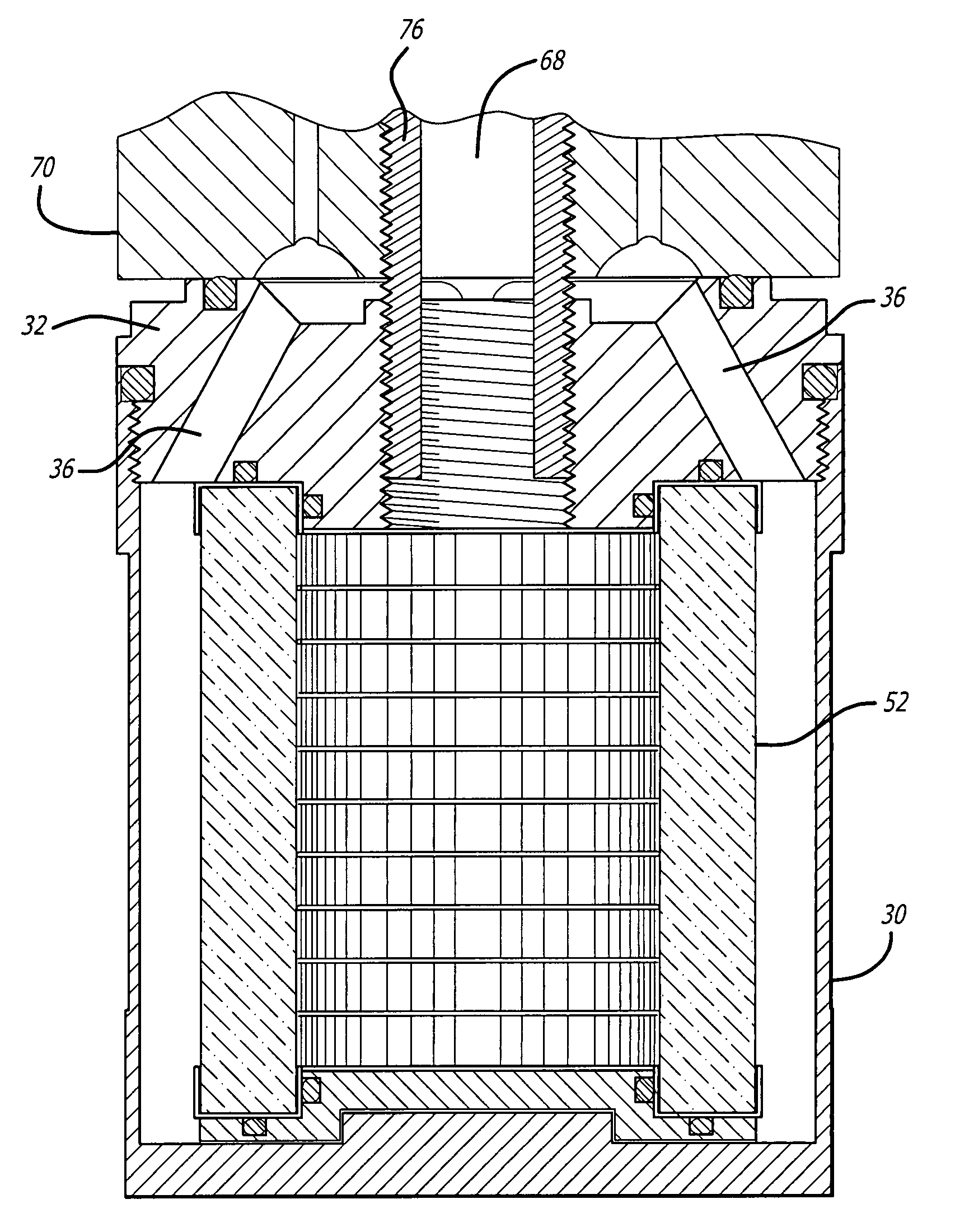
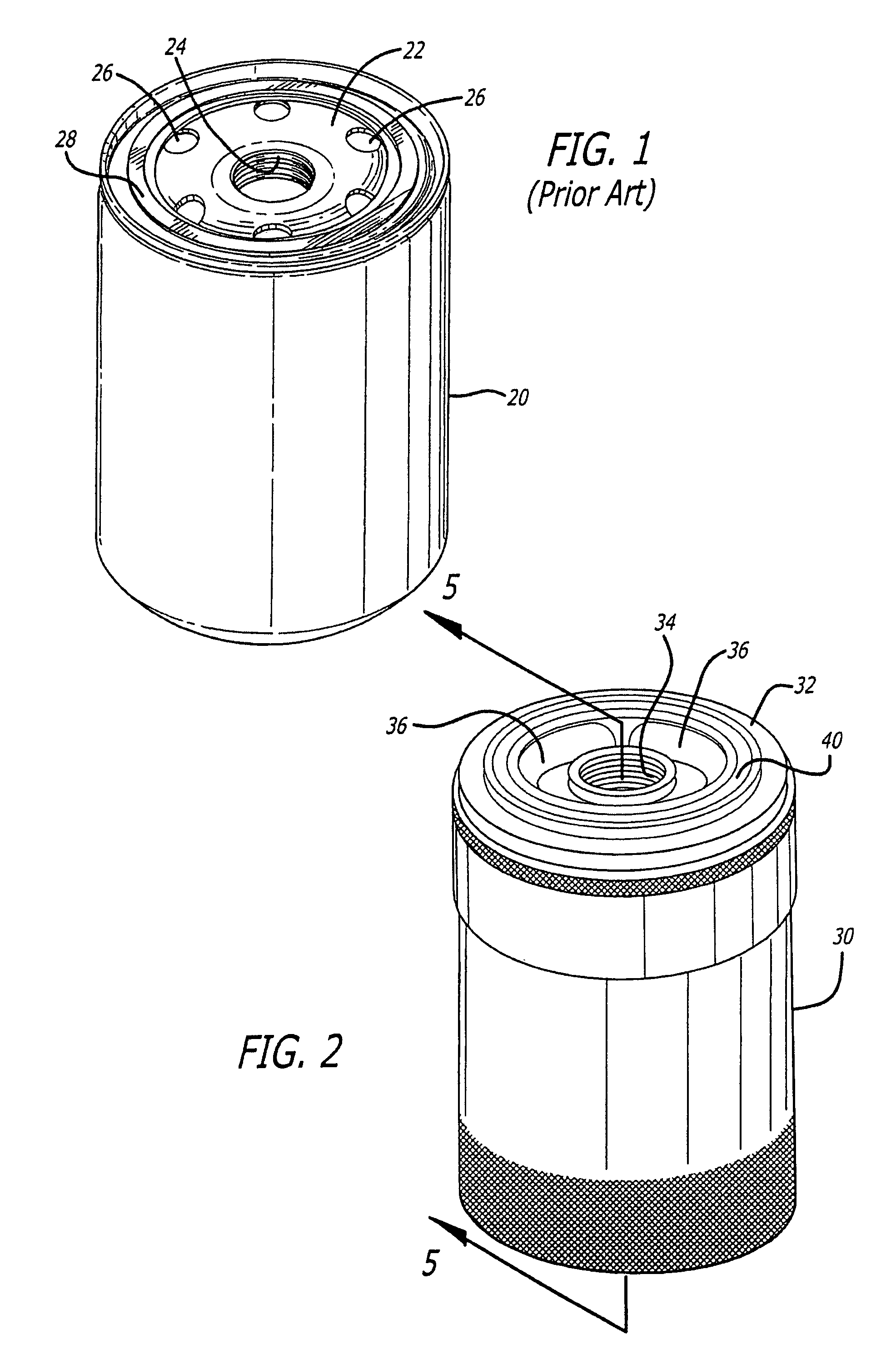
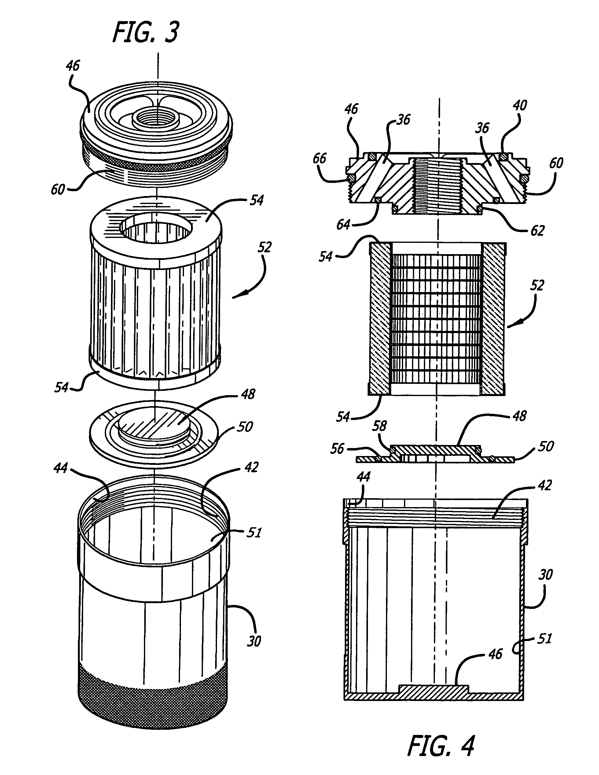
[0015]First referring to FIG. 2, a perspective view of one embodiment of the present invention may be seen. The filters and methods of the present invention are intended to provide a direct replacement for the prior art filters of the type shown in FIG. 1, and accordingly may be substituted for such prior art filters with absolutely no change to the internal combustion engine itself, and more particularly, with no change to the oil filter mount. Thus, the filter shown in FIG. 2 has a physical appearance very similar to that of the prior art filter of FIG. 1, being characterized in appearance by a can-like housing 30 and a top cap 32, having an internally threaded central hub 34 and openings 36 through the top cap 32 within the periphery of a rubber or elastomeric seal ring 40. However, internally the oil filters of the present invention are very different from the prior art, as may be seen in FIGS. 3 and 4.

[0016]FIG. 3 presents an exploded perspective view of the embodiment of FIG. ...


PUM

PropertyMeasurementUnit
pressureaaaaaaaaaa
sizesaaaaaaaaaa
sizeaaaaaaaaaa

Abstract

A replacement filter for conventional throw-away spin-on oil filter cartridge on an internal combustion engine. The replacement filter uses a porous metallic filter element, preferably a woven stainless steel, pleated filter element, within a housing physically simulating the conventional throw-away spin-on oil filter cartridge. The housing is disassembleable, typically by unscrewing the top cap of the housing, for removal, cleaning and reuse of the filter element. This avoids the problems of cost and availability of replacement filters and of disposal of used filters. Various embodiments are disclosed.

Description

BACKGROUND OF THE INVENTION[0001]1. Field of the Invention[0002]The present invention relates to the field of oil filters, and more particularly to oil filters as are frequently used on internal combustion engines.[0003]2. Prior Art[0004]Internal combustion engines, including gasoline and diesel engines as are commonly used in cars, trucks, boats and stationary power plants, frequently use a canister type oil filter for filtering the crankcase oil as it circulates through the pressure lubrication system. A typical filter of this type may be seen in FIG. 1. Such filters are characterized by a can-like housing 20 with a top cap 22 permanently attached thereto having an internally threaded center region or hub 24, openings 26 and a flat rubber seal 28. Within the can-like housing 20 and separating the center region in communication with the opening through hub 24 and the outer region in communication with the openings 26 is a pleated paper filter material through which oil may pass. In...

Claims


Application Information

Patent Timeline
Patent Type & Authority Patents(United States)
IPC IPC(8): B01D27/00B01D27/06B01D27/10
CPCB01D27/06B01D29/21B01D35/30B01D29/96B01D35/147B01D2201/302Y10S210/17
Inventor TIDWELL, KELLY
Owner HAMMOND ENTERPRISES INC
Learn More