
Concrete block system

a technology of concrete blocks and blocks, applied in the field of concrete blocks, can solve the problems of preventing the realization of natural stone appearance, affecting the versatility and capability of existing concrete blocks, and affecting the efficiency of mass production,

Active Publication Date: 2008-08-12
OLDCASTLE BUILDING PROD CANADA INC
View PDF10 Cites 86 Cited by
  • Summary
  • Abstract
  • Description
  • Claims
  • Application Information

AI Technical Summary

Benefits of technology

"The invention is a dry-cast concrete block system that can be used in various structures such as walls, columns, and steps. The system includes a support block and a face block that are coupled together using a special coupling part. The face block has a natural stone appearance and can be used to create a textured surface. The system can be embedded in material to be retained by a retaining wall or used in steps. The technical effect of this invention is to provide a durable and visually appealing block system for use in various structures."

Problems solved by technology

This monolithic character often detrimentally affects versatility of existing concrete blocks and their capability to accommodate design constraints of structures to be constructed.
Wet-cast concrete blocks may have a natural stone appearance realized directly during casting, but relatively long production times and requirements for numerous molds typically render impractical their efficient mass-production.
However, these relatively short production times impose constraints on a degree of surface irregularity that may be imparted to dry-cast concrete blocks during casting, thereby preventing realization of a natural stone appearance during casting.
Dry-cast concrete blocks are thus typically subjected after casting to a mechanical artificial aging / weathering process (e.g., tumbling, splitting / breaking, object impacting, etc.) to realize desired natural stone characteristics, which decreases production efficiency.

Method used


Image

  • Concrete block system
  • Concrete block system
  • Concrete block system

Examples


Embodiment Construction

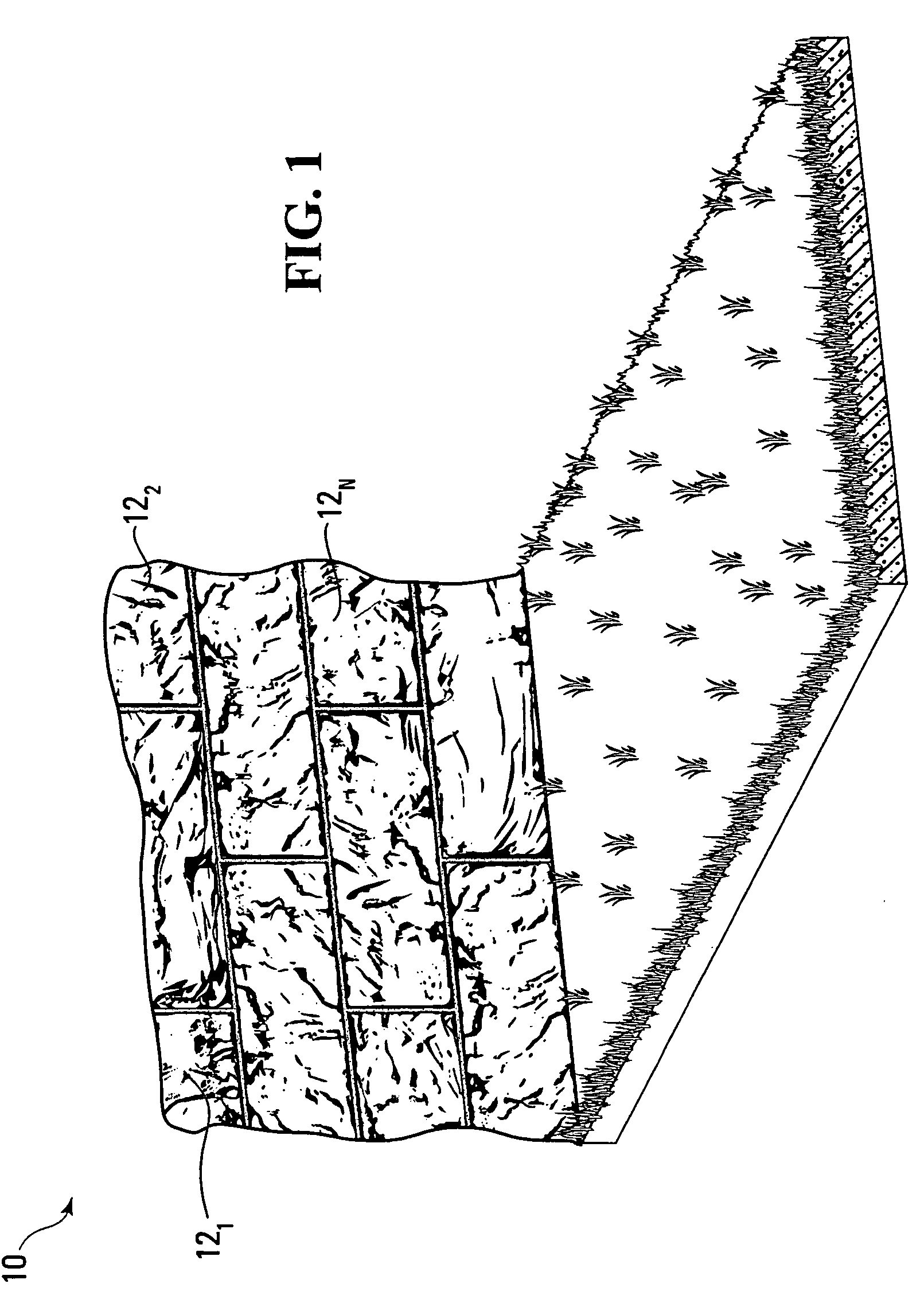
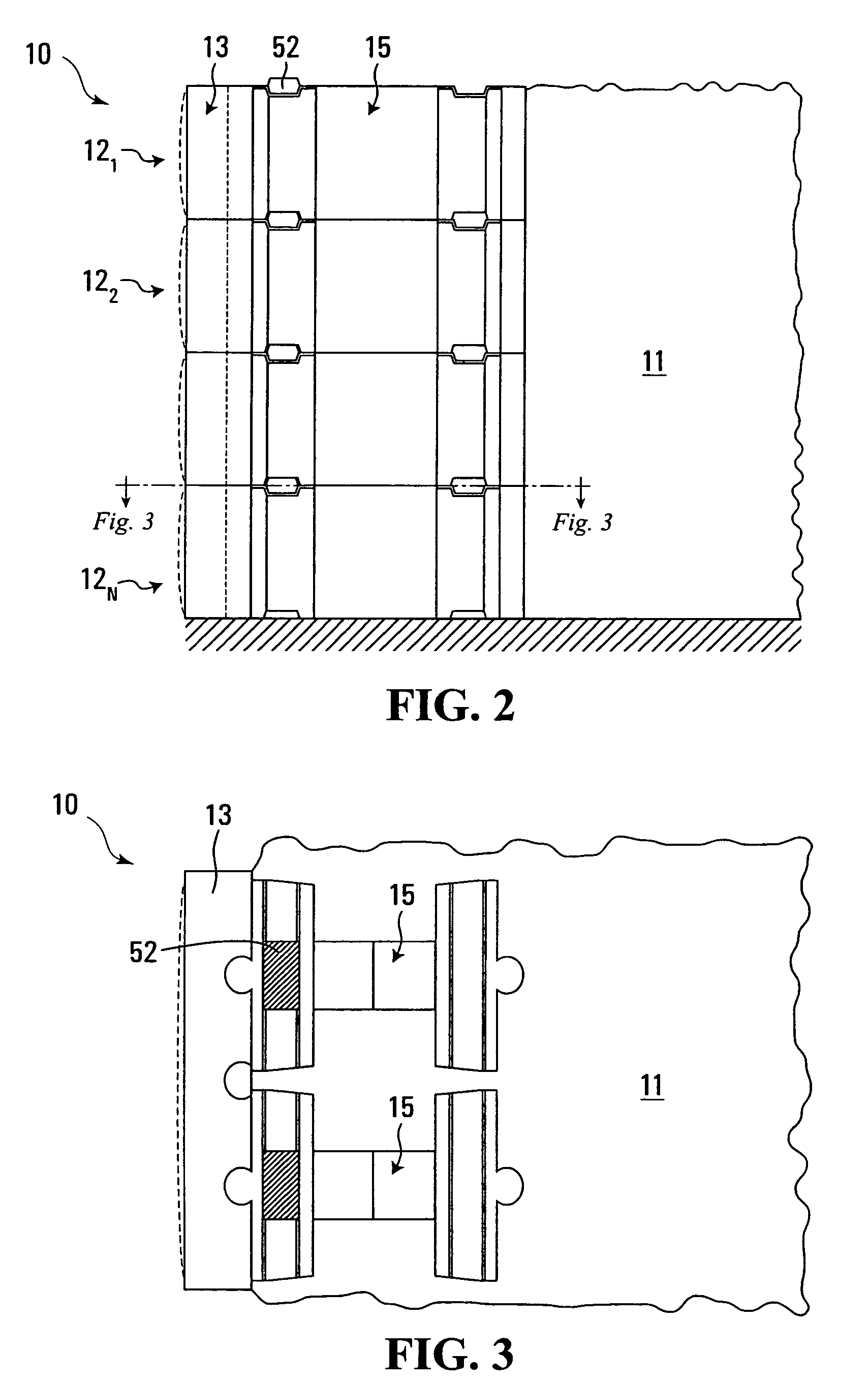
[0033]FIGS. 1 to 3 show a wall portion 10 comprising a plurality of concrete block systems 121 . . . 12N in accordance with an embodiment of the invention. In this embodiment, the wall portion 10 is part of a retaining wall that holds back material 11 such as soil, drainage aggregate, etc. The concrete block systems 121 . . . 12N can thus be referred to as retaining wall block systems.

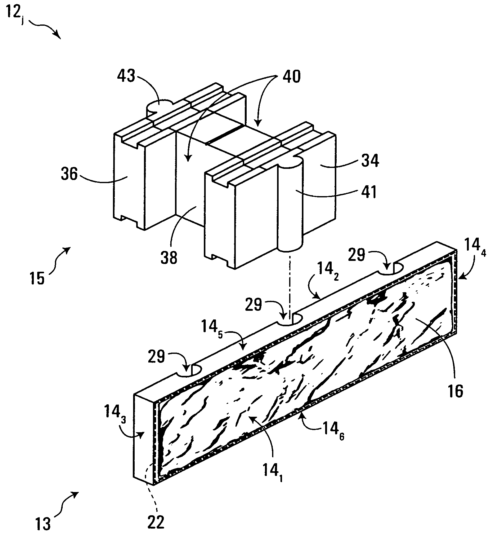
[0034]With additional reference to FIG. 4, there is shown a given concrete block system 12; of the concrete block systems 121 . . . 12N (1≦j≦N). In this embodiment, the concrete block system 12j comprises a face block 13 adapted to be coupled to a support block 15.

[0035]The face block 13 is intended to be at least partly exposed when the concrete block system 12j is positioned in the wall portion 10, i.e., the face block 13 has a surface adapted to be exposed when the face block 13 is coupled to the support block 15. In this embodiment, the face block 13 is a dry-cast concrete block, i.e., it is made o...


PUM


Abstract

A dry-cast concrete block system for use in a structure. The dry-cast concrete block system comprises a support block comprising a first coupling part and a face block comprising a second coupling part. The first coupling part and the second coupling part enable the face block to be coupled to the support block. The face block comprises a surface adapted to be exposed when the face block is coupled to the support block and the dry-cast concrete block system is positioned in the structure. In one embodiment, at least a portion of the surface has a cast texture with a natural stone appearance. In one embodiment, the structure is a wall and the concrete block system is a wall block system. For example, the wall may be a retaining wall and the wall block system may be a retaining wall block system. In another embodiment, the structure is a column and the concrete block system is a column block system. In yet another embodiment, the structure is steps and the concrete block system is a steps block system.

Description

FIELD OF THE INVENTION[0001]The present invention relates to concrete blocks, in particular those with a natural stone appearance, that may be used in walls, columns, steps and other types of structures.BACKGROUND[0002]Concrete blocks intended to serve as wall blocks (e.g., retaining wall blocks), column blocks, step blocks or other types of structural blocks are sometimes provided with a natural stone appearance over an exposed portion thereof. Such concrete blocks can then be assembled into walls, columns, steps or other structures that have a natural and aesthetic look.[0003]While various configurations, sizes and looks exist, these concrete blocks are conventionally monolithic elements made of various types of concrete. This monolithic character often detrimentally affects versatility of existing concrete blocks and their capability to accommodate design constraints of structures to be constructed.[0004]Also, depending on their constituent concrete, concrete blocks can be broadl...

Claims


Application Information

Patent Timeline
Patent Type & Authority Patents(United States)
IPC IPC(8): E02D29/02
CPCE02D29/0266E02D29/025
Inventor HAMEL, DENIS
Owner OLDCASTLE BUILDING PROD CANADA INC
Learn More