
Elastomeric fabric load bearing surface

a technology of load bearing surface and elastomeric fabric, which is applied in the direction of sofas, beds, chairs, etc., can solve the problems of unintended negative impact on comfort and unsatisfactory body support applications, and achieve the effects of high degree of regional control over the overall profile, increased support, and increased deflection

Active Publication Date: 2008-08-05
ILLINOIS TOOL WORKS INC
View PDF13 Cites 59 Cited by
  • Summary
  • Abstract
  • Description
  • Claims
  • Application Information

AI Technical Summary

Benefits of technology

The solution provides a comfortable, ventilated, and lightweight load bearing surface that mimics conventional cushion support characteristics, reducing pressure points and enhancing support without compromising comfort, suitable for seating applications.

Problems solved by technology

Although elastomeric fabric surfaces can be quite comfortable in many applications, they are not ideal in all body-support applications.
Some ergonomists refer to this type of deflection as “hammocking” and consider it undesirable because it can cause the hips to rotate upward.
This rotation of the hips can cause discomfort, particularly over extended periods.
Although this can reduce the amount of deflection that occurs under load (and therefore reduce the degree of hammocking), it can have an unintended negative impact on comfort.

Method used


Image

  • Elastomeric fabric load bearing surface
  • Elastomeric fabric load bearing surface
  • Elastomeric fabric load bearing surface

Examples


Embodiment Construction

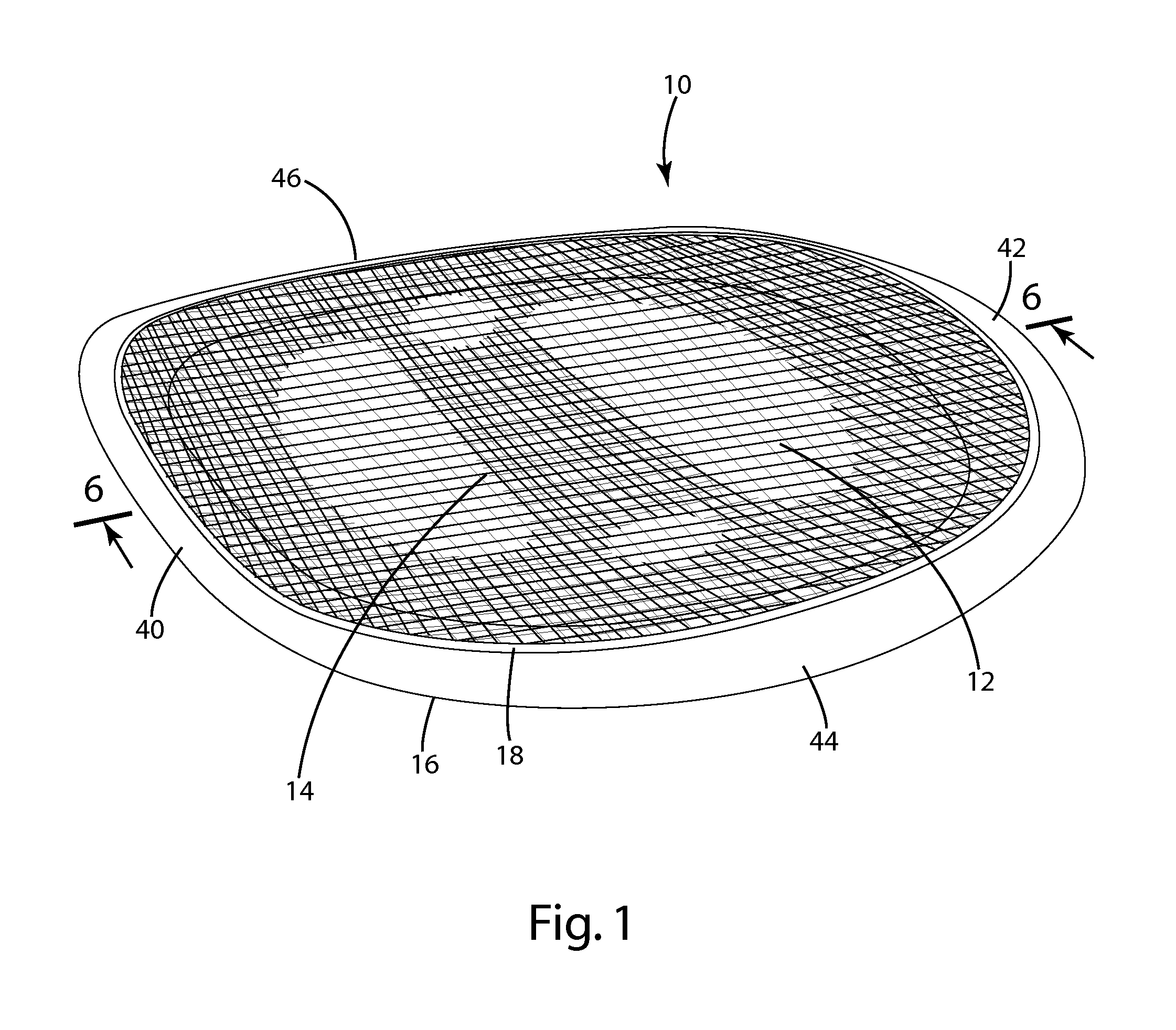
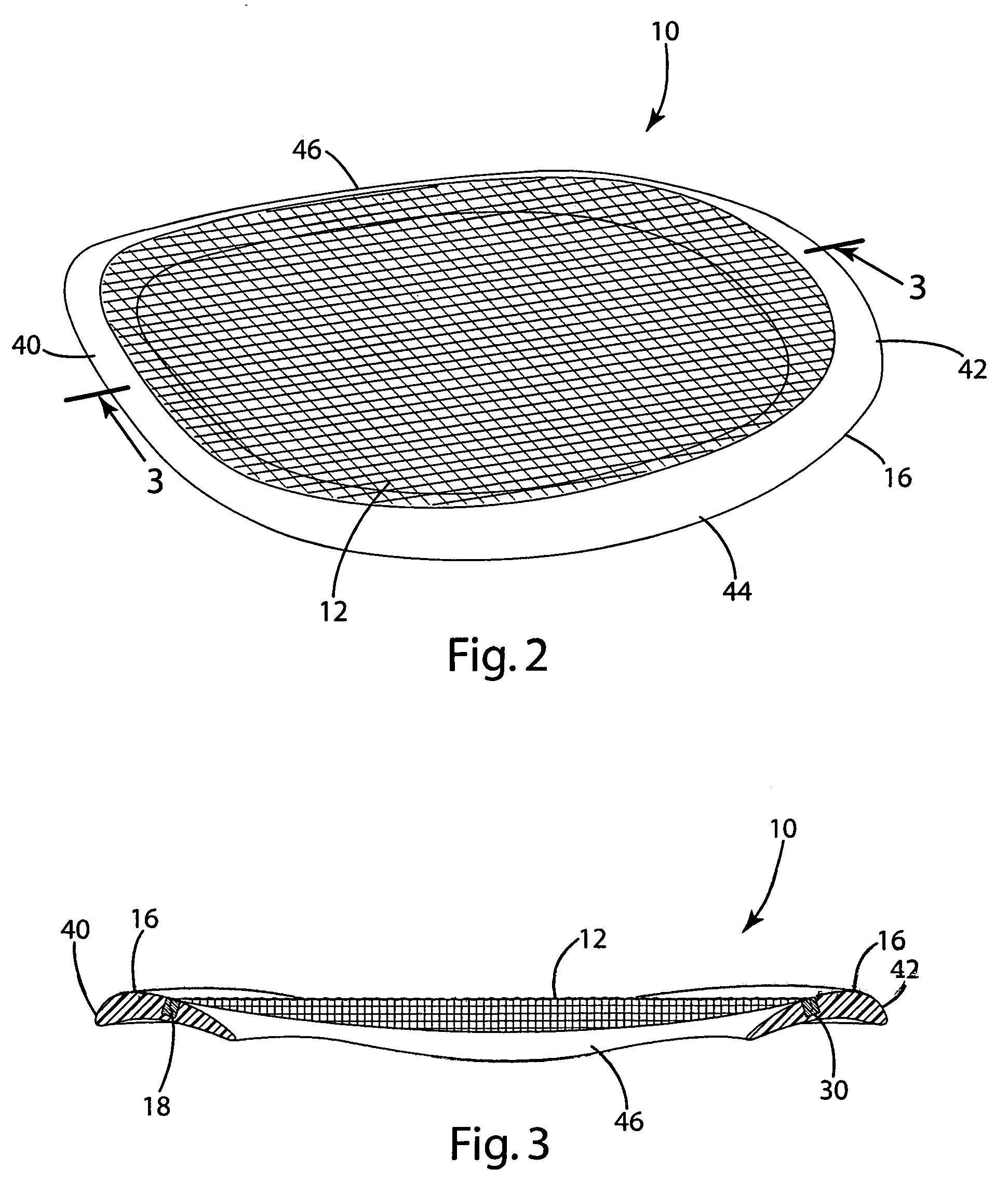
[0025]A load bearing surface 10 according to one embodiment of the present invention is shown in FIG. 1. The load bearing surface 10 shown in FIG. 1 is intended for use as a chair seat, and it includes an upper layer 12 and a lower layer 14 that are suspended from a chair seat frame 16. The frame 16 may in turn be mounted to a chair pedestal (not shown). The upper layer 12 is stretched over the lower layer 14 and is deflectable under a load. As the upper layer 12 increasingly deflects under a load (not shown), the lower layer 14 is increasingly engaged. As a result, the two layers 12 and 14 cooperate to define the overall force / deflection profile of the load bearing surface 10. For purposes of disclosure, the present invention is described in connection with various alternative embodiments intended primarily for use in seating applications. The present invention is not, however, limited to use in seating applications, but may also be incorporated into other load bearing applications...


PUM


Abstract

An elastomeric fabric load bearing surface having a non-linear force / deflection profile. In one embodiment, the load bearing surface includes multiple layers, at least one of which is an elastomeric fabric. The various layers cooperate with one another to define a non-linear force / deflection profile. In one embodiment, the load bearing surface includes an upper layer of elastomeric fabric and a lower layer of elastomeric fabric, and the two layers are stretched in different directions. In a second aspect, the load bearing surface includes at least one layer of elastomeric fabric that follows a non-linear pattern. In one embodiment of this second aspect, the fabric defines a body-supporting surface and includes a plurality of undulations away from the body-supporting surface.

Description

BACKGROUND OF THE INVENTION[0001]The present invention relates to load bearing surfaces, and more particularly to elastomeric fabric load bearing surfaces, such as the seat or back of a chair or bench, or the support surface of a bed, cot or other similar body-supporting product.[0002]There is a continuing effort to develop new and improved load bearing surfaces for use in body-supporting applications, such as the support surfaces in seating, cots and beds. It is desirable for load bearing surfaces to be, among other things, comfortable, durable and relatively inexpensive to manufacture and assemble.[0003]There is an increasing use of elastomeric load bearing fabrics in the seating industry. For example, there are a variety of office chairs available from well-known suppliers that include seat and back portions manufactured from elastomeric fabric. In a conventional application of this type, a layer of elastomeric fabric is stretched across a frame over an opening. In use, the elast...

Claims


Application Information

Patent Timeline
Patent Type & Authority Patents(United States)
IPC IPC(8): A47C7/02
CPCA47C7/282A47C7/022A47C7/029A47C7/28A47C7/02
Inventor COFFIELD, TIMOTHY P.SOMMERFELD, DANIEL S.WARD, JOSEPH D.
Owner ILLINOIS TOOL WORKS INC
Learn More