
Device and method for encapsulation and mounting of RFID devices

a technology of rfid devices and housings, applied in the field of encapsulation and mounting of rfid devices, can solve the problems of preventing the transmission and reception of radio frequency (rf) signals by the rfid devices, and affecting the operation of the burglar alarm

Active Publication Date: 2008-07-29
UNITED PARCEL SERVICE OF AMERICAN INC
View PDF25 Cites 39 Cited by
  • Summary
  • Abstract
  • Description
  • Claims
  • Application Information

AI Technical Summary

Benefits of technology

[0010]The present invention overcomes many of the challenges encountered in the art by combining RFID technology with the process of encapsulation, and by the use of a spacing or stand-off device for mounting an RFID device. According to one embodiment of the invention, an RFID device such as, for example, an RFID transponder, is encapsulated by known domed encapsulation techniques to conceal the RFID device and form a protected RFID device for use in harsh environments. Furthermore, the embodiments of this invention provide a domed encapsulated RFID apparatus and method of forming the same, such that interference, attenuation and absorption of the radio frequency (RF) signal by the encapsulating material and by any surface on which the encapsulated RFID device is placed is minimized.
[0011]The packaging of RFID devices performs several functions, including environmental protection and concealment. However, the packaging material should be compatible with the RF performance of the tag to avoid degradation of the performance of the RFID system. The present invention involves encapsulating a standard RFID tag in a manner that will protect or conceal the RFID tag. Because of its use in artwork and labeling, domed encapsulation is relatively inexpensive. An economical way to encapsulate an RFID device is by using a domed polyester or polyurethane process.
[0012]In one embodiment of the invention, a spacing device holds an RFID device a distance away from a mounting surface so that RF interference caused by the mounting surface or nearby materials is lessened.
[0021]Yet another aspect of this invention is an encapsulated RFID device comprised of one or more materials having certain thicknesses such that interference with RF signals is minimized.

Problems solved by technology

RFID transponders may be exposed to a variety of harsh environments during the course of their use.
Although RFID devices generally are packaged in a plastic housing, these housings may lack sufficient properties to withstand harsh environments for prolonged periods.
Some of these surfaces that are comprised of materials such as, for example, various metals, impede or block the transmission and reception of radio frequency (RF) signals by the RFID devices.
In other instances, materials proximate to the surface on which the RFID device is mounted may impede the transmission and reception of RF signals by the RFID device.

Method used


Image

  • Device and method for encapsulation and mounting of RFID devices
  • Device and method for encapsulation and mounting of RFID devices
  • Device and method for encapsulation and mounting of RFID devices

Examples


Embodiment Construction

[0057]The present invention now will be described more fully hereinafter with reference to the accompanying drawings, in which some, but not all, embodiments of the invention are shown. Indeed, this invention may be embodied in many different forms and should not be construed as limited to the embodiments set forth herein; rather, these embodiments are provided so that this disclosure will satisfy applicable legal requirements. Like numbers refer to like elements throughout.

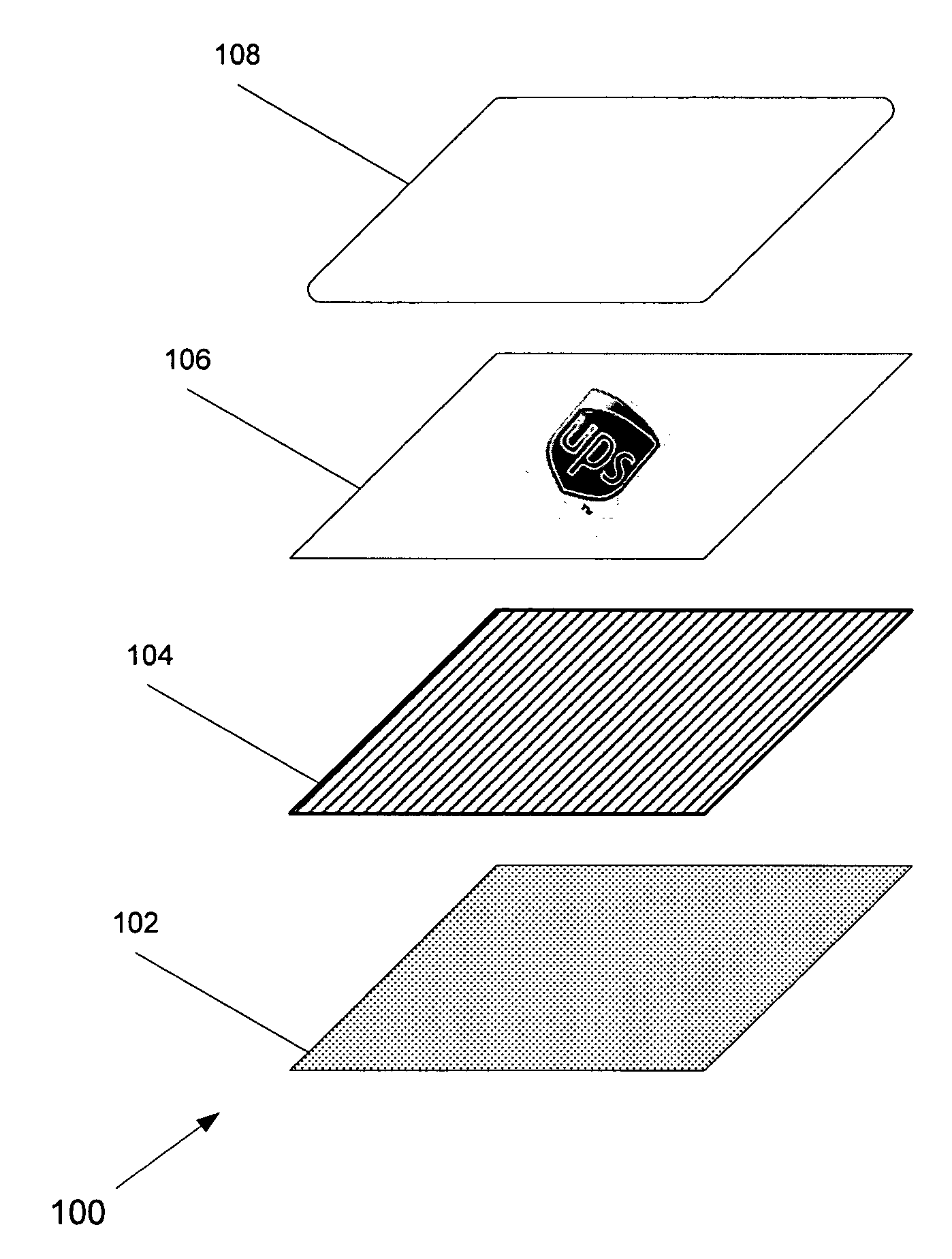
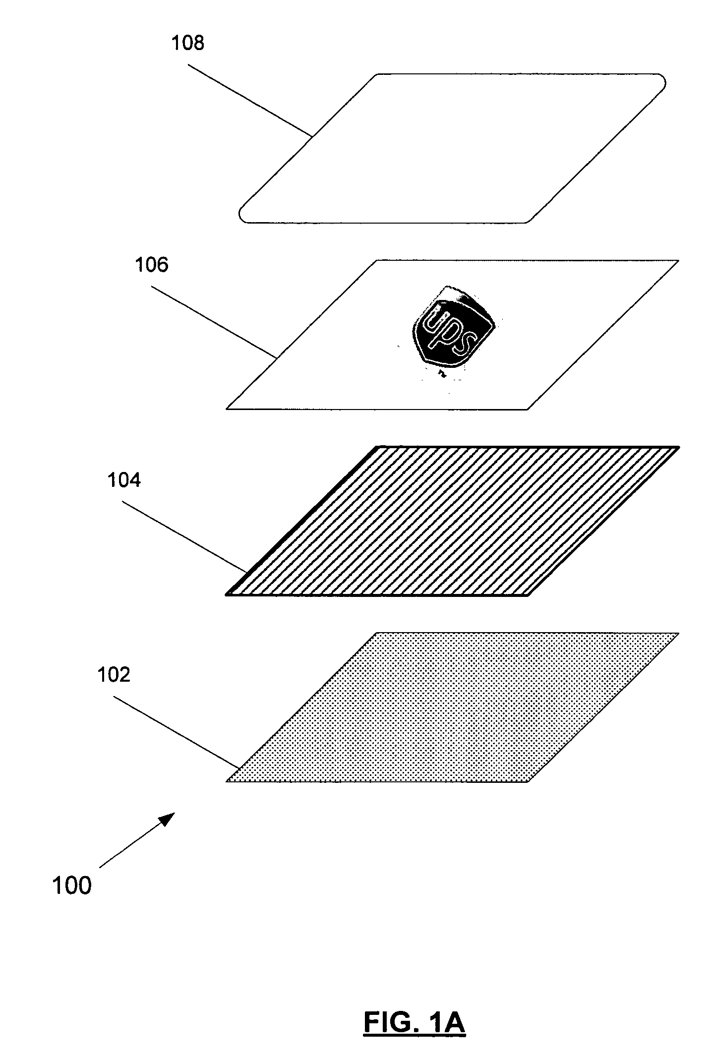
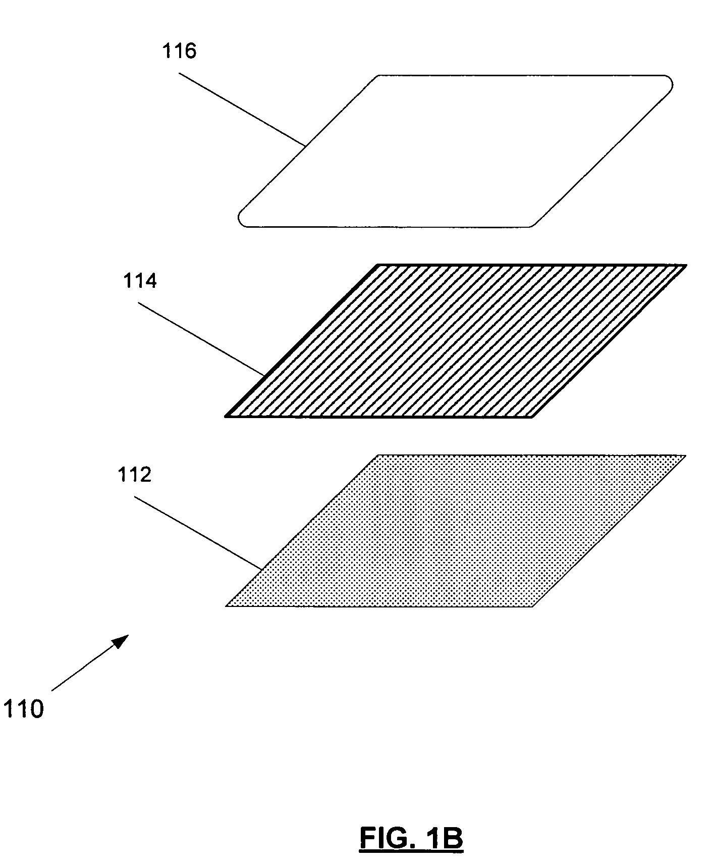
[0058]FIG. 1A is an exploded view of the components that comprise an exemplary domed encapsulated RFID tag 100 in an embodiment of the invention. In this embodiment, an adhesive layer 102 comprised of an approximately 2 millimeter (mil) thick acrylic adhesive liner is substantially attached to and underlies an RFID device 104, though other thicknesses and types of adhesive may be used. In one embodiment, this adhesive layer 102 has an adhesive on its exposed surface such that it can be adhesively mounted to anoth...


PUM

PropertyMeasurementUnit
thicknessesaaaaaaaaaa
frequencyaaaaaaaaaa
translucentaaaaaaaaaa

Abstract

This invention involves encapsulating an RFID device in an encapsulating material by known encapsulating processes to form a domed, encapsulated RFID tag. The encapsulating material may be translucent or opaque, flexible or hard, and has minimal effect on transmission or reception of radio frequency (RF) signals. The invention further involves a stand-off bracket, composed of one or more materials that have minimal effect on transmission or reception of RF signals, for mounting an RFID device on or near materials that impede RF transmission and reception. The encapsulated RFID tag and stand-off bracket, separately, may have an adhesive or other attachment means on one of their surfaces so that they may be adhered or otherwise attached to another surface. In one application, an encapsulated RFID tag in the 860-928 MHz range is mounted on a stand-off bracket and may be used for tracking items to which it is attached.

Description

CROSS-REFERENCE TO RELATED APPLICATIONS[0001]This application claims the benefit of U.S. Provisional Application Nos. 60 / 540,508, filed Jan. 30, 2004, and 60 / 544,455, filed Feb. 13, 2004.BACKGROUND OF THE INVENTION[0002]1. Field of the Invention[0003]The present invention relates generally to radio frequency identification (RFID) devices and, more particularly, to the encapsulation and mounting of RFID devices. Specifically, the present invention relates to the domed encapsulation of RFID transponders and their mounting on surfaces that impede radio frequency (RF) transmissions.[0004]2. Description of Related Art[0005]Radio frequency identification (RFID) is an information acquisition technology. RFID systems are generally designed to manage assets of many types. RFID systems are generally comprised of transponders (a / k / a “tags”), a transmitter to provide energy to the tags, a receiver to receive transmissions from the transponders, and a computer system to process the received info...

Claims


Application Information

Patent Timeline
Patent Type & Authority Patents(United States)
IPC IPC(8): G08B13/14A61F13/15B29C45/14B29C65/00G06K19/06H01L23/02H01L23/28H01L23/29H01P11/00H01R43/00G06K17/00G06K19/077
CPCG06K19/07749G06K19/0776G08B13/2417G08B13/2437G08B13/2434Y10T29/49117Y10T156/10Y10T29/49016
Inventor OLSEN, JOHN
Owner UNITED PARCEL SERVICE OF AMERICAN INC
Learn More