
Method and system for performing digital beam forming at intermediate frequency on the radiation pattern of an array antenna

a technology of array antennas and radiation patterns, applied in the field of methods and systems for controlling the radiation pattern of array antennas at intermediate frequencies, can solve the problems of complex realization and integration into base stations or transceiver terminals, confidential and restricted information, and poor beam-shaping capability

Active Publication Date: 2008-07-22
TELECOM ITALIA SPA +1
View PDF10 Cites 93 Cited by
  • Summary
  • Abstract
  • Description
  • Claims
  • Application Information

AI Technical Summary

Benefits of technology

The present invention provides an improved method and system for beam forming using intermediate frequency signals. This approach allows for the use of digital signal processing capabilities to achieve the same beam shape as traditional methods, while also being applicable to every kind of beam forming system. The invention is non-intrusive and can be used in a manufacturer-independent manner. Overall, the invention allows for improved beam forming performance and efficiency.

Problems solved by technology

This solution, however, presents many drawbacks, as its beam-shaping capability is poorly versatile.
Phase shifter in particular, which are implemented as Butler matrices, are quite complex systems, whose realization and integration into base stations or transceiver terminals can be complicated.
In fact, usually, and particularly with regard to telecommunication apparatuses, this is a confidential and restricted information of the manufacturer.

Method used


Image

  • Method and system for performing digital beam forming at intermediate frequency on the radiation pattern of an array antenna
  • Method and system for performing digital beam forming at intermediate frequency on the radiation pattern of an array antenna
  • Method and system for performing digital beam forming at intermediate frequency on the radiation pattern of an array antenna

Examples


Embodiment Construction

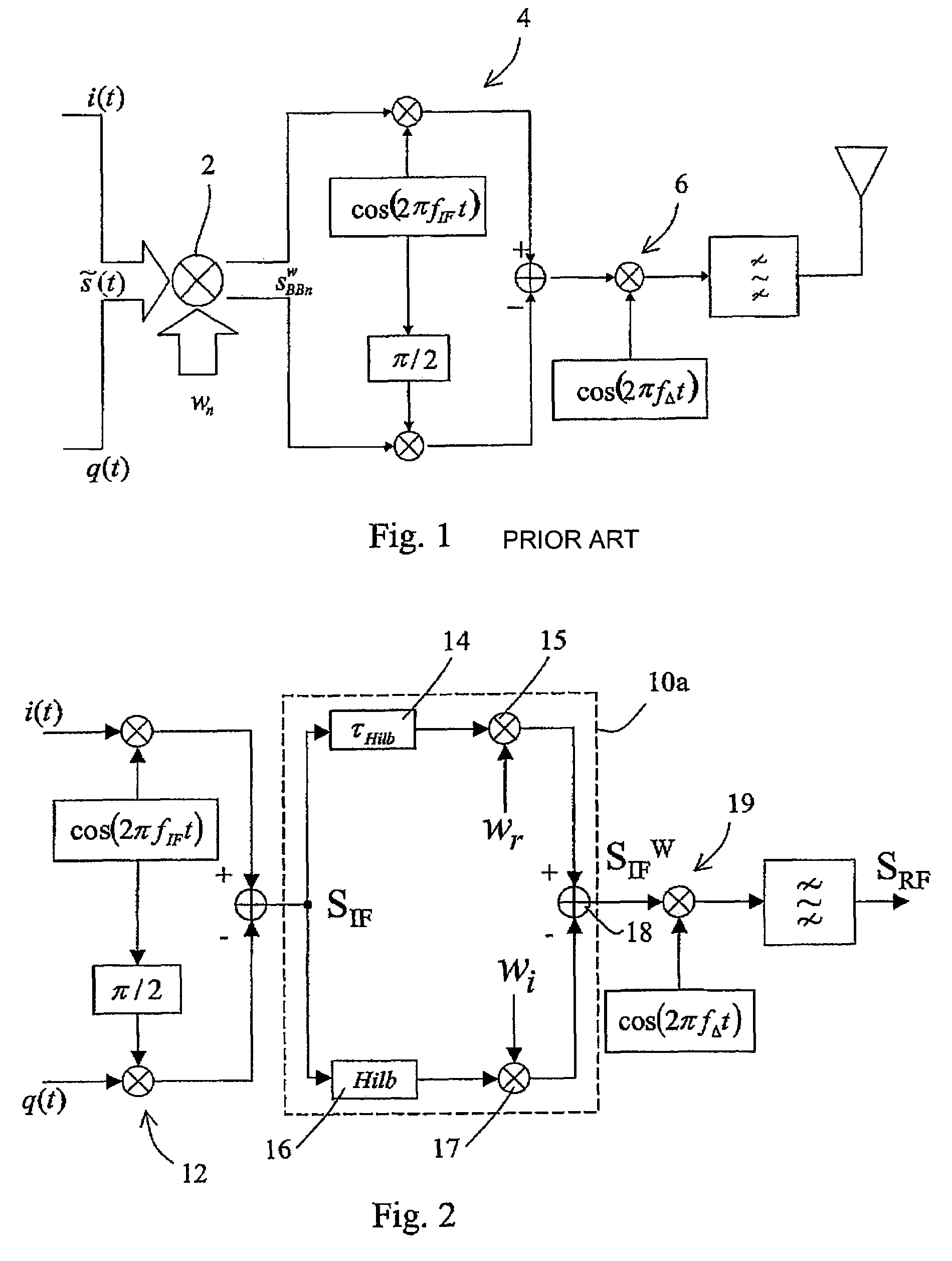
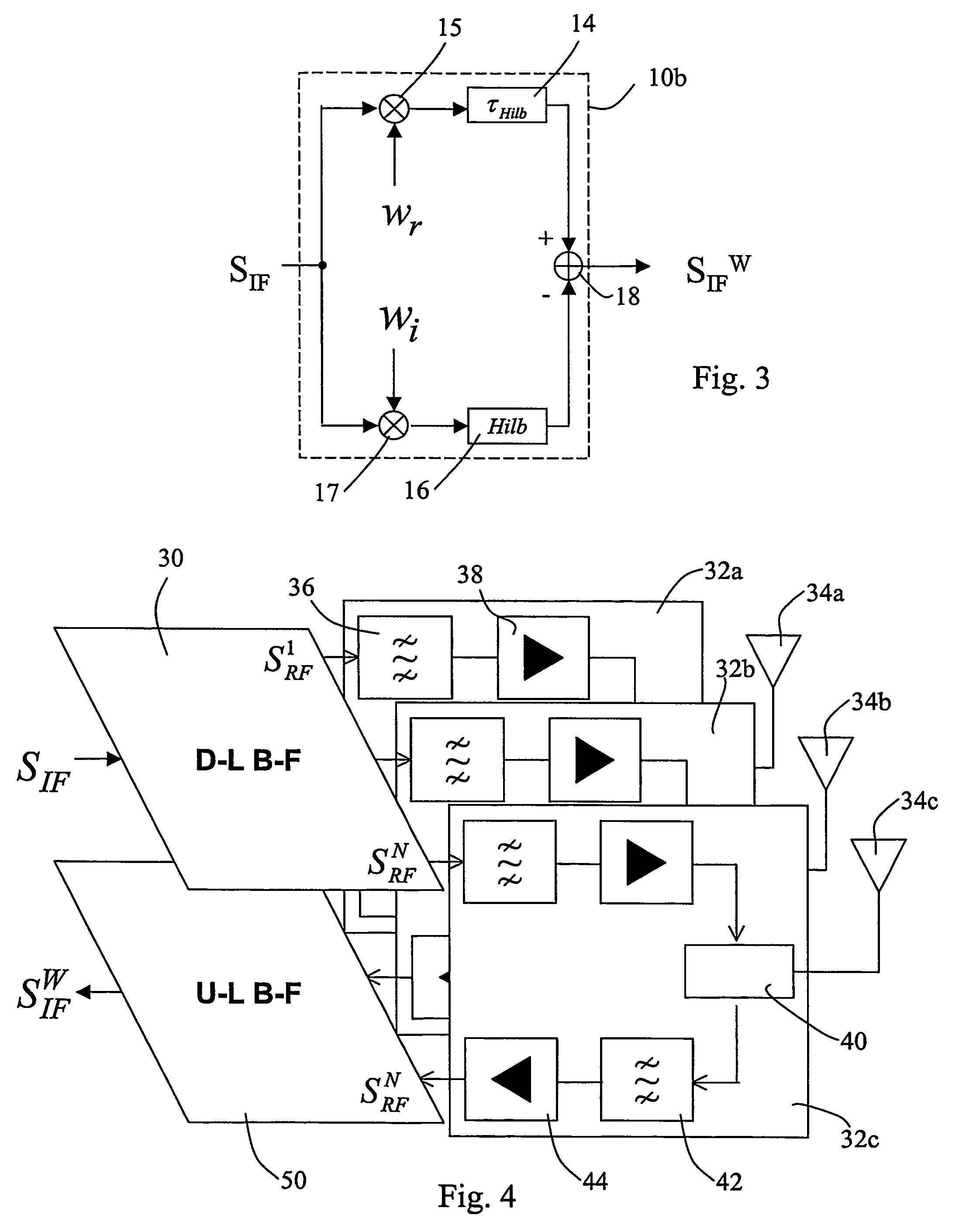
[0041]A first exemplary schematic diagram of a digital beam forming processing system realised according to the present invention is shown in FIG. 2. An intermediate frequency IF signal SIF, obtained for example by up-conversion 12 from a base band input signal {tilde over (s)}(t)=i(t)+jq(t), is processed by a beam forming block 10a, for obtaining an output weighted IF signal SIFW. The output signal SIFW is then up-converted 19 to a radio frequency signal SRF, according to well known techniques.

[0042]The operation of beam forming block 10a will now be explained in detail. The SIFW signal, centred at frequency fIF, feeding the n-th antenna element of an array antenna, can be expressed as

sIFnw(t)=Re{wn{tilde over (s)}(t)exp(j2πfIFt)}

[0043]where Wn is the n-th complex weight and {tilde over (s)}(t)=i(t)+jq(t) is the complex envelope of the IF signal. The previous equation can be rewritten as:

[0044]sIFnw⁡(t)=wrn⁢Re⁢{s~⁡(t)⁢exp⁡(j⁢⁢2⁢⁢π⁢⁢fIF⁢t)}+win⁢Re⁢{s~⁡(t)⁢exp⁡(j⁢⁢2⁢⁢π⁢⁢fIF⁢t+π / 2)}=w...


PUM


Abstract

A method of performing digital beam forming on the radiation pattern of an array antenna using a plurality of antenna elements, each antenna element being coupled to a signal processing chain. A weighting phase is used in which at least a complex weight coefficient is applied to a digital signal in a corresponding signal processing chain. The digital signal is an intermediate frequency digital signal, and the weighting phase has the following steps: a) duplicating the digital signal into a first and a second digital signal; b) processing the first and second digital signals by multiplying the first and second digital signals respectively by a real and an imaginary part of the complex weight coefficient; applying a Hilbert transform to that signal which is multiplied by the imaginary part of the complex weight coefficient; and c) combining the processed first and second digital signals into a weighted digital intermediate frequency signal by subtracting the second signal from the first signal.

Description

CROSS REFERENCE TO RELATED APPLICATION[0001]This application is a national phase application based on PCT / EP2003 / 012089, filed Oct. 30, 2003, the content of which is incorporated herein by reference.FIELD OF THE INVENTION[0002]The present invention refers to a method and a system for controlling the radiation pattern of an array antenna at intermediate frequency (IF) through digital processing.[0003]Array antennas are very attractive solutions whenever beamshaping capability is needed. The beamshape control in array antennas can be accomplished with by manipulating signals at different stages of the transceiver chain.[0004]Even if array antennas have many fields of application, mobile communications are preferred, but not exclusive, ones. In fact, in a mobile communication system the capability of adjusting cell borders and size is certainly a major key factor, especially if it can be performed remotely from a centralised location. As an example, it allows to efficiently cope with t...

Claims


Application Information

Patent Timeline
Patent Type & Authority Patents(United States)
IPC IPC(8): H01Q3/00H01Q3/26H04B7/04H04B7/06H04B7/08
CPCH01Q3/2605H04B7/086H04B7/0617H04B7/0408
Inventor COPPI, FRANCESCOCROZZOLI, MAURIZIODISCO, DANIELESCOTTI, RENATO
Owner TELECOM ITALIA SPA
Learn More