
Connector assembly

a technology of connectors and assemblies, applied in the direction of rod connections, manufacturing tools, mechanical devices, etc., can solve the problem of insufficient longitudinal stability of the structur

Inactive Publication Date: 2008-07-15
BANTA BRADFORD C
View PDF8 Cites 37 Cited by
  • Summary
  • Abstract
  • Description
  • Claims
  • Application Information

AI Technical Summary

Benefits of technology

[0009]More particularly, it is the object of the invention to provide a connector assembly of the aforementioned character, which is uniquely designed to provide both longitudinal and transverse stability to the structure formed by the interconnected structural members.
[0011]Another object of the invention is to provide a connector assembly of the character described in the preceding paragraphs which includes strategically located, are spaced apart through bolts that extend through the opposing brackets and through each structural member to further improve rigidity.
[0013]Another object of the invention is to provide a connector assembly of the type described in the previous paragraphs in which each of the gripping plates is lanced out to form a plurality of penetrating tabs that are adapted to penetrate the structural members as the gripping plates are cinched down by the through bolts so as to provide still further rigidity to the assembled structure.

Problems solved by technology

A drawback of certain of the prior art connector assemblies resides in the fact that the connector assemblies, while providing generally lateral stability to the structure that embodies the connector assembly often fails to provide adequate longitudinal stability to the structure.

Method used


Image

  • Connector assembly
  • Connector assembly
  • Connector assembly

Examples


Embodiment Construction

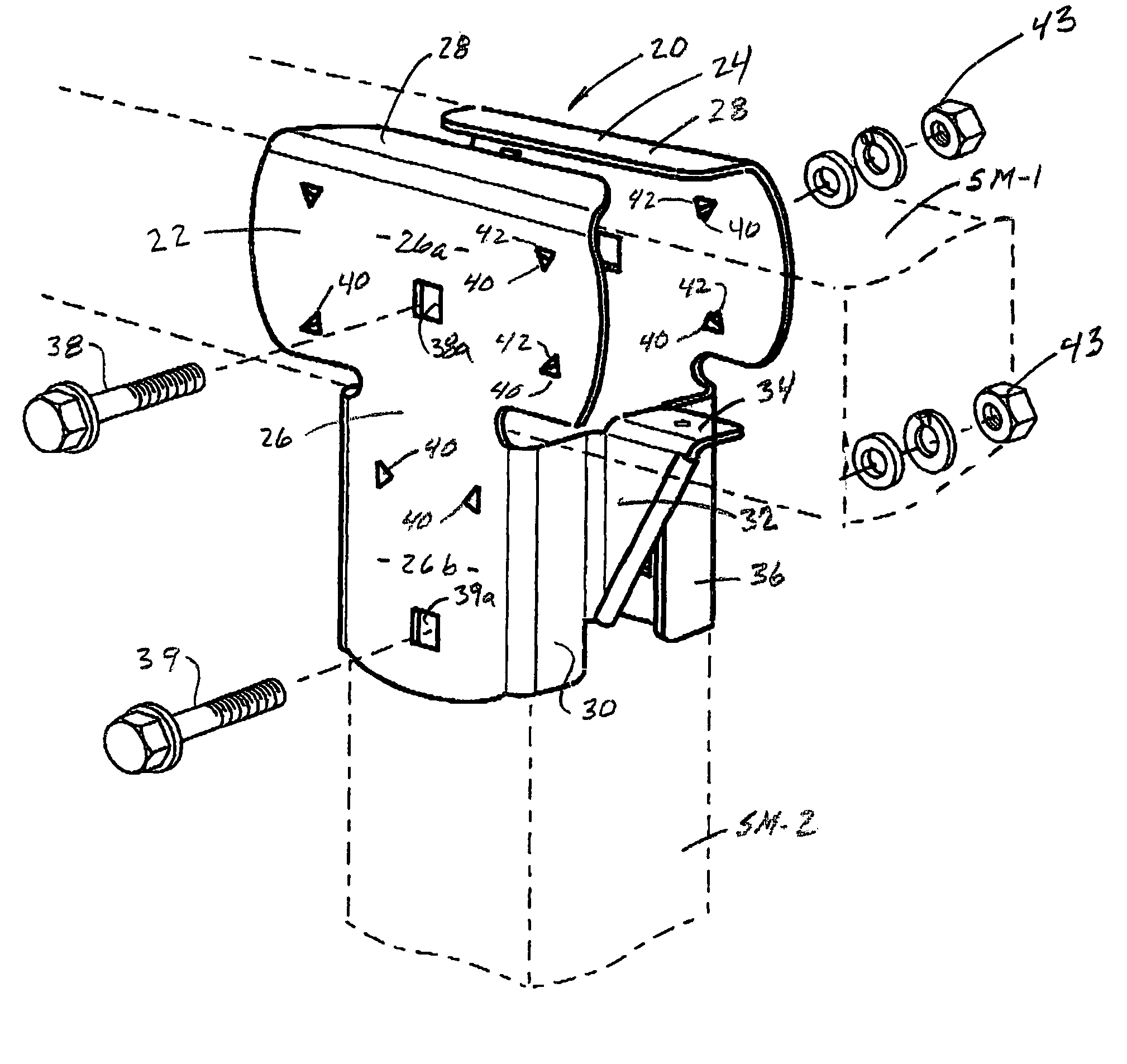
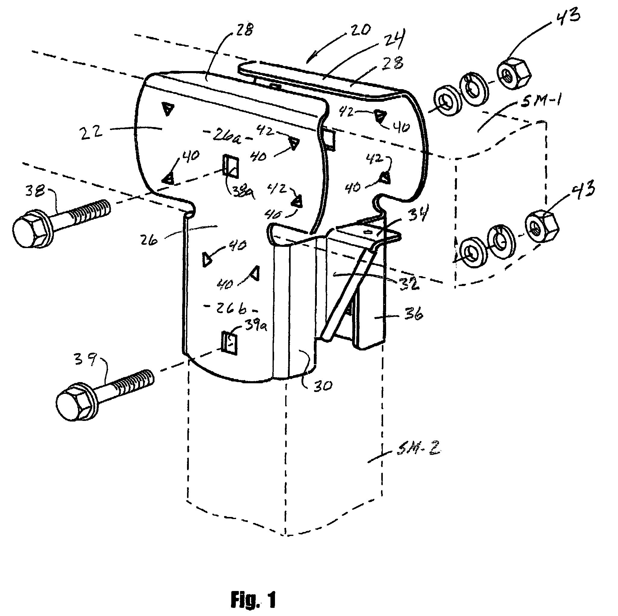
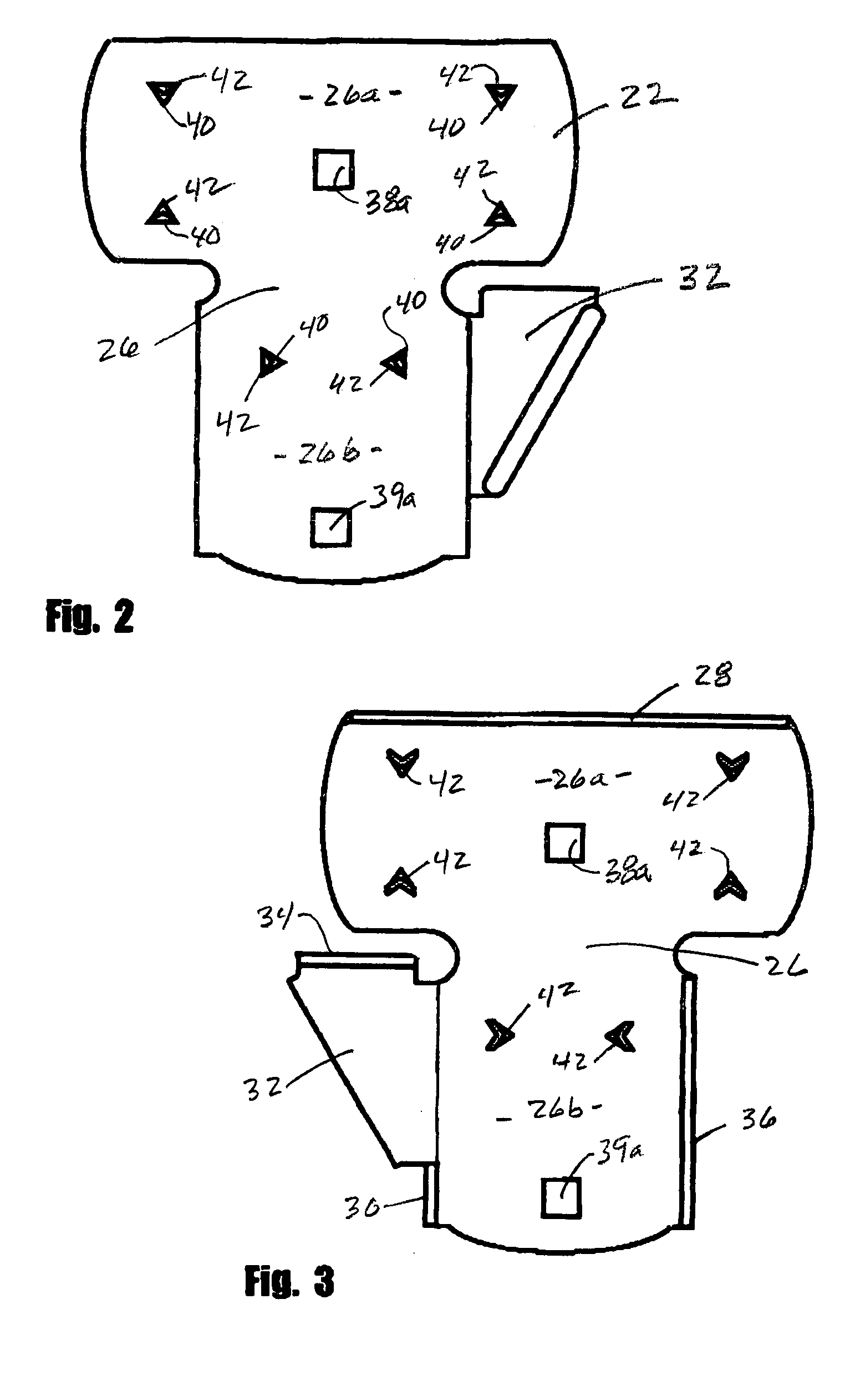
[0033]Referring to the drawings and particularly in FIGS. 1 through 7, one form of the bracket assembly of the invention for interconnecting first and second elongate structural members is there illustrated and generally designated by the numeral 20. The bracket assembly here comprises first and second cooperating brackets 22 and 24 and connector means for interconnecting the cooperating brackets. Brackets 22 and 24 are of identical construction and each comprises a generally planar surface 26 having a first generally rectangularly shaped portion 26a and second generally rectangularly shaped portion 26b. As indicated in figure 1, first portion 26a engages the first elongate structural member SM-1 and the second portion 26b engages the second elongate structural member SM-2. In this instance, structural members SM-1 and SM-2 are wooden beams which extend generally perpendicularly relative to one another.

[0034]Extending generally perpendicularly from first portion 26a of planar surfac...


PUM


Abstract

A connector assembly for use in securely joining together elongated structural members, which extend angularly with respect to one another. The connector assembly is ideally suited for use in interconnecting wooden structural members that make up playground equipment for use by young children and includes specially designed connector plates that are uniquely designed to provide both longitudinal and transverse stability to the structure formed by the interconnected structural members. Each of the gripping plates is lanced out to form a plurality of penetrating tabs that are adapted to penetrate the structural members as the gripping plates are cinched down by through bolts so as to provide still further rigidity to the assembled structure.

Description

BACKGROUND OF THE INVENTION[0001]1. Field of the Invention[0002]The present invention relates generally to structural connectors. More particularly, the invention concerns a flanged connector assembly for use in connecting together elongated structural members that extend at an angle with respect to one another.[0003]2. Discussion of Prior Art[0004]Various types of connectors have been suggested in the past for joining together structural members, such as lengths of dimension lumber, structural wood beams, and the like. Often the prior art connectors take the form of clamp assemblies that are used to join together perpendicularly arranged structural member to form permanent and temporary structures such as scaffolds and playground structures.[0005]As a general rule the prior art clamp assemblies comprise shaped gripping members that are formed of sheet metal by a combination of cutting, punching, stamping and bending operations. The formed gripping members are typically apertured to...

Claims


Application Information

Patent Timeline
Patent Type & Authority Patents(United States)
IPC IPC(8): E04B7/04B25G3/00E04B1/38E04B1/26F16B7/00F16B15/00
CPCE04B1/2608F16B7/00Y10T403/4614Y10T403/4617F16B15/0046F16B7/0486
Inventor BANTA, BRADFORD C.
Owner BANTA BRADFORD C
Learn More