
Coulter counter having a plurality of channels

a technology of a capacitor counter and a plurality of channels, which is applied in the field of multichannel particle counting methods, can solve the problems of increasing the resistance of the channel, extending the measurement time substantially, and low throughput efficiency

Inactive Publication Date: 2008-07-08
THE UNIVERSITY OF AKRON
View PDF12 Cites 62 Cited by
  • Summary
  • Abstract
  • Description
  • Claims
  • Application Information

AI Technical Summary

Benefits of technology

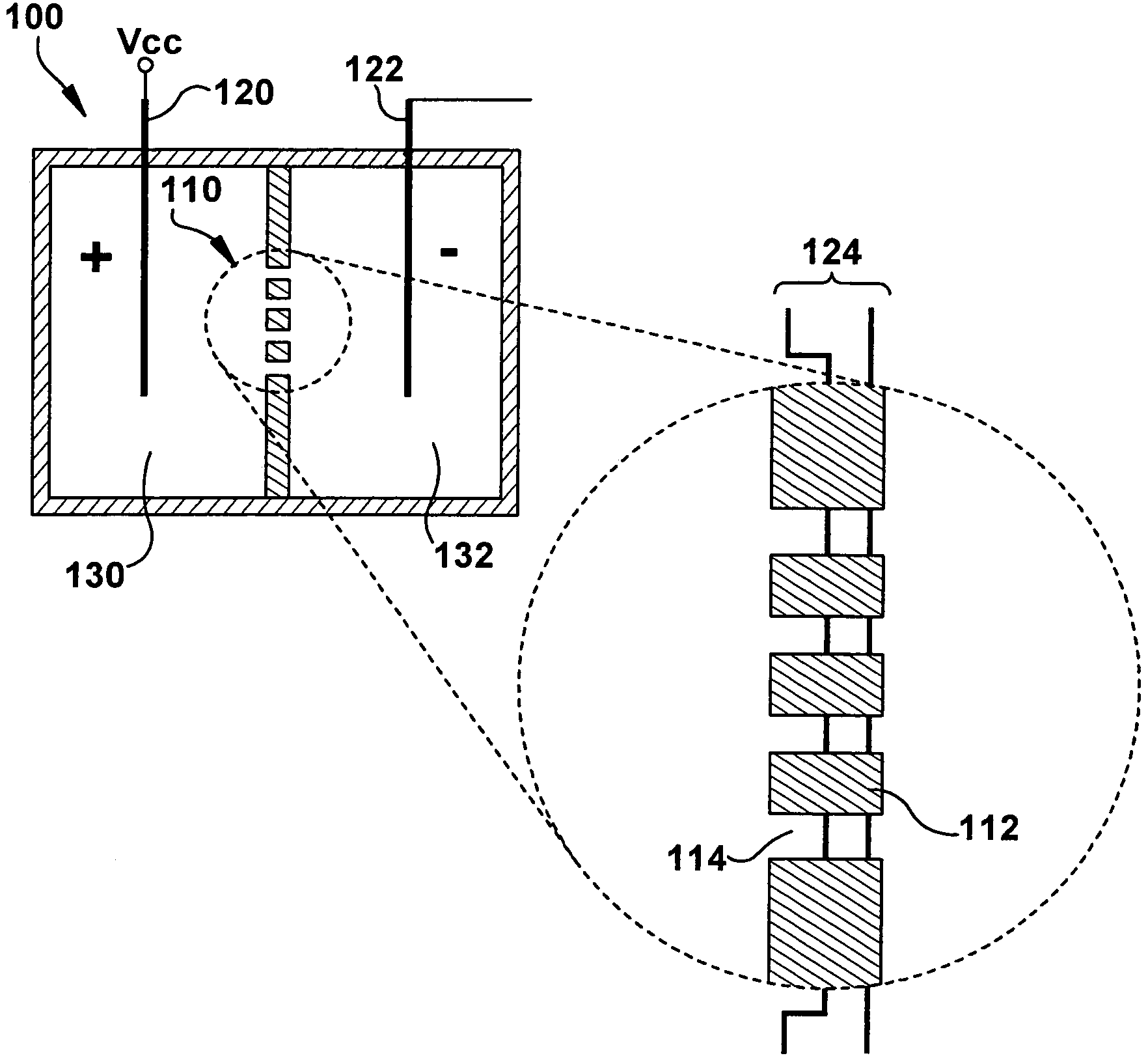
The present invention is a device that can quickly count particles by using a membrane with multiple small openings. Each opening has a control electrode that is electrically isolated from the others. The membrane has one electrode in communication with a power supply and the other electrode in communication with a measuring circuit. The device is filled with an electrolyte solution. The method involves charging one reservoir with particles, applying a voltage across the electrodes, allowing the particles to move from one reservoir to the other through the openings, detecting the signals generated by the particles, deconvoluting the signals, and counting the signals. The device can correlate the signals to a number of particles.

Problems solved by technology

More particularly, as a particle passes through a channel, it disrupts the ion current therein, thus increasing the channel's resistance.
One substantial disadvantage of existing Coulter counters is their low throughput efficiency, which substantially extends measurement times. Coulter counting measurement relies on particles passing through a tiny orifice (microchannel) one by one from one chamber to the other.
Thus, in order to complete sampling of a small number of particle solutions, thousands of micro or nanoparticles have to pass through the orifice one by one, which could be prohibitively time consuming.
However, both methods have fallen short.
Particularly, in order to obtain a sufficient fluid velocity, a strong external electric field must be applied leading to high power consumption, which is not practical for most biological applications.
Furthermore, electroosmosis and electrophoresis only drive charged particles.
Thus, if the particles are only slightly charged or neutral, electric forces are too weak to substantially shorten measurement time.
Accordingly, there is a deficiency in the art in that it lacks a high throughput particle counting method and device, which is compatible with biological particles.

Method used


Image

  • Coulter counter having a plurality of channels
  • Coulter counter having a plurality of channels
  • Coulter counter having a plurality of channels

Examples


example of pollen detection embodiment

[0074]One working example of the present invention is set forth as follows. Four types of micro-scale particles are chosen for a test of a multi-aperture sensor embodiment. They are polymethacrylate (PM) particles with diameters of 40 μm and 20 μm, Rocky Mountain Juniper (Juniper Scopulorum) pollen, and Cottonwood pollen. All particles are obtained from Sigma Aldrich, Inc. PM particles are chosen because they are commercially available and have well-characterized properties. The diameters of the pollen particles are determined using high-resolution optical microscopy, and range from 17.5 μm to 22.5 μm for the Juniper pollen and 20 μm for Cottonwood pollen. FIG. 8 shows photomicrographs of the four types of particles.

[0075]For experiments involving the polymethacrylate (PM) particles, 40 μm and 20 μm particle solutions can be prepared by diluting 0.1 mL of the original solution, which has 10% solid content, in 2 mL and 10 mL of deionized water, respectively. The estimated particle co...


PUM

PropertyMeasurementUnit
voltageaaaaaaaaaa
voltageaaaaaaaaaa
volumeaaaaaaaaaa

Abstract

The present invention generally relates to a method for rapidly counting micron and / or submicron particles by passing such particles through any of a plurality of orifices simultaneously with an ion current and measuring the signal generated thereby. The present invention also generally relates to a device for practicing the method of the present invention. Some embodiments can include methods and / or devices for distinguishing between and counting particles in mixtures. Still other embodiments can include methods and / or devices for identifying and / or counting bioparticles and / or bioactive particles such as pollen.

Description

RELATED APPLICATION DATA[0001]This application claims priority to U.S. Provisional Patent Application No. 60 / 729,262 filed Oct. 21, 2005 now pending, which is incorporated herein by reference in its entirety.[0002]Development of this invention is funded United States Government grant Nos. NSF DMR 0210508 and NIH R15 DK61316-01. The U.S. Government may have certain rights in this invention.BACKGROUND OF THE INVENTION[0003]The present invention is generally related to a multichannel particle counting method and a device for practicing the method. Such counters can be used to count micro-scale and / or nano-scale particles and the like. Counters within the scope of the present invention generally operate by sensing changes in resistance, conductivity, conductance or the like. More particularly, as a particle passes through a channel, it disrupts the ion current therein, thus increasing the channel's resistance.[0004]Quantitative measurements of the size and concentration of micro and nan...

Claims


Application Information

Patent Timeline
Patent Type & Authority Patents(United States)
IPC IPC(8): G01N27/00G01N15/00
CPCG01N15/1056G01N15/12G01N15/1245G01N15/1023G01N15/134
Inventor HU, JUNZHE, JIANG
Owner THE UNIVERSITY OF AKRON
Learn More