
Drill rig and a method for controlling a fan therein

a technology of a drill rig and a fan, which is applied in the direction of engine cooling apparatus, vehicle heating/cooling devices, air-conditioning devices, etc., can solve the problems of fan sound level, pronounced sound level in the driver's cab, and the risk of overheating of the cooling elemen

Inactive Publication Date: 2008-07-08
EPIROC ROCK DRILLS AB
View PDF13 Cites 2 Cited by
  • Summary
  • Abstract
  • Description
  • Claims
  • Application Information

AI Technical Summary

Benefits of technology

This approach reduces stress on components, increases service life, lowers noise and fuel consumption, and maintains optimal fluid temperatures, allowing drill rigs to operate effectively in colder climates without overcooling.

Problems solved by technology

The problem with the above-mentioned way of controlling, or to be precise, not controlling the fans, is that the cooling elements that have lower cooling demand than what the fans provide run the risk of becoming overcooled, above all when the drill rig is used in cold climates.
An additional disadvantage of letting the fan operate at a constantly high rotation speed (highest power) is that the sound level from the fans and thereby also the sound level in the driver's cab is pronounced.

Method used


Image

  • Drill rig and a method for controlling a fan therein
  • Drill rig and a method for controlling a fan therein
  • Drill rig and a method for controlling a fan therein

Examples


Embodiment Construction

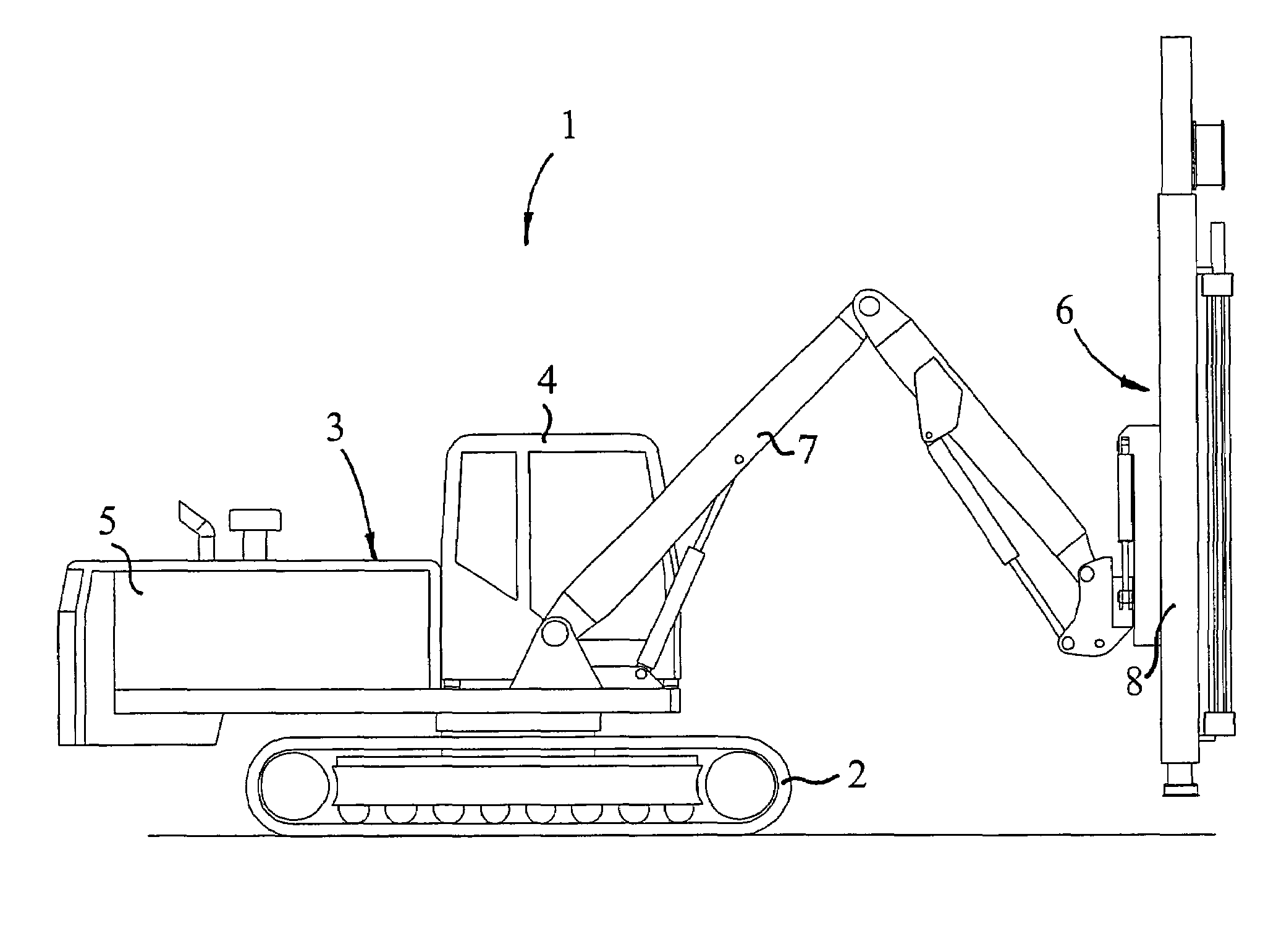
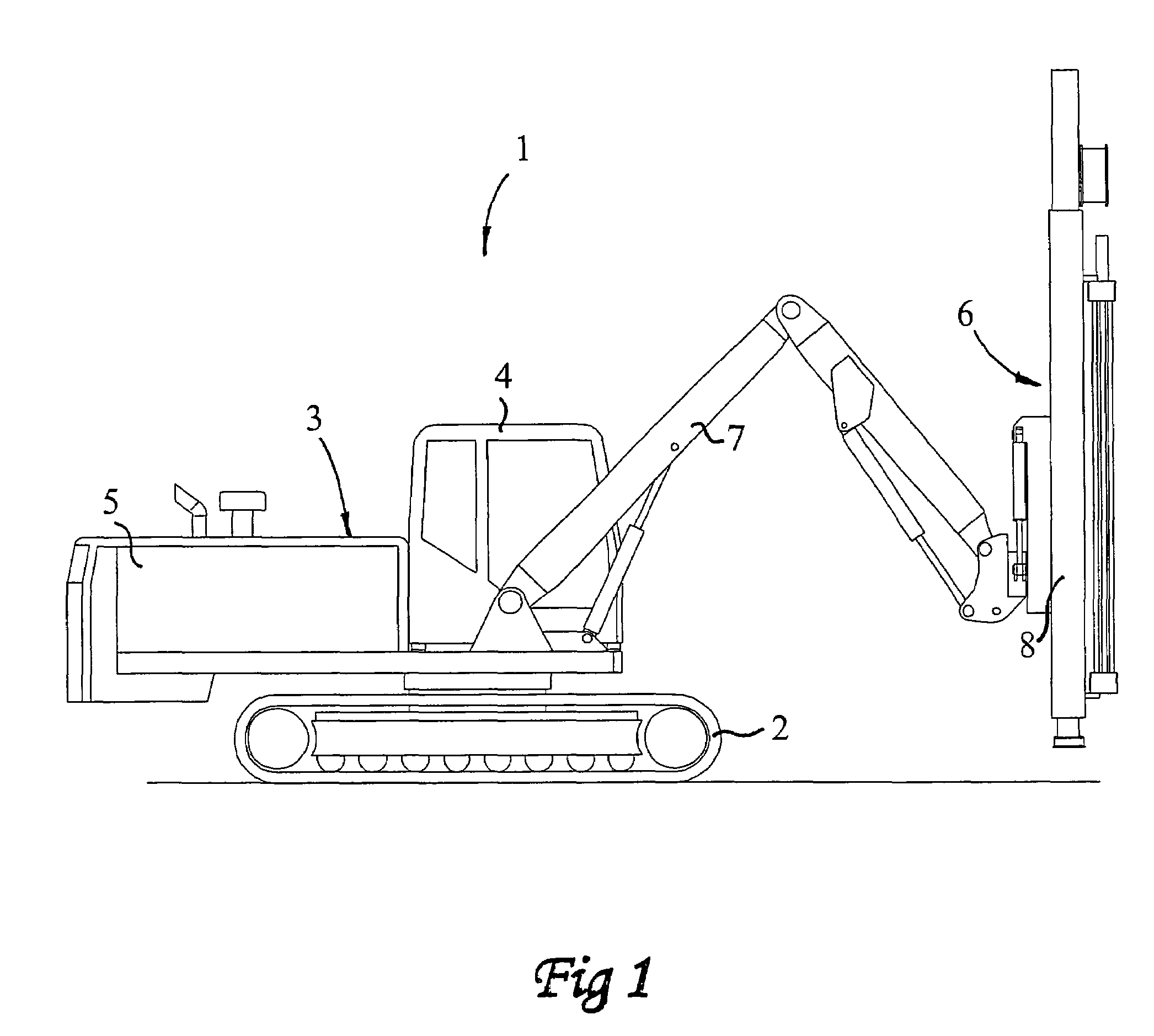
[0017]In FIG. 1, a drill rig according to the invention is shown, generally designated 1. The drill rig 1 comprises a carrier 3 carried by a pair of caterpillars 2, or the like, and comprising a driver's cab 4 and an engine house-forming chassis 5. The engine house 5 is in no way tight but comprises holes and openings so that good circulation of air therein is allowed. In the front part of the carrier 3, a feeder 6 is arranged, which is carried by one or more bars 7 and which comprises a drilling equipment 8, which is carried by the bars 7. The radius of working and accessibility of the drill rig 1 is determined by the bars 7 and the drilling equipment 8, which are of conventional type.

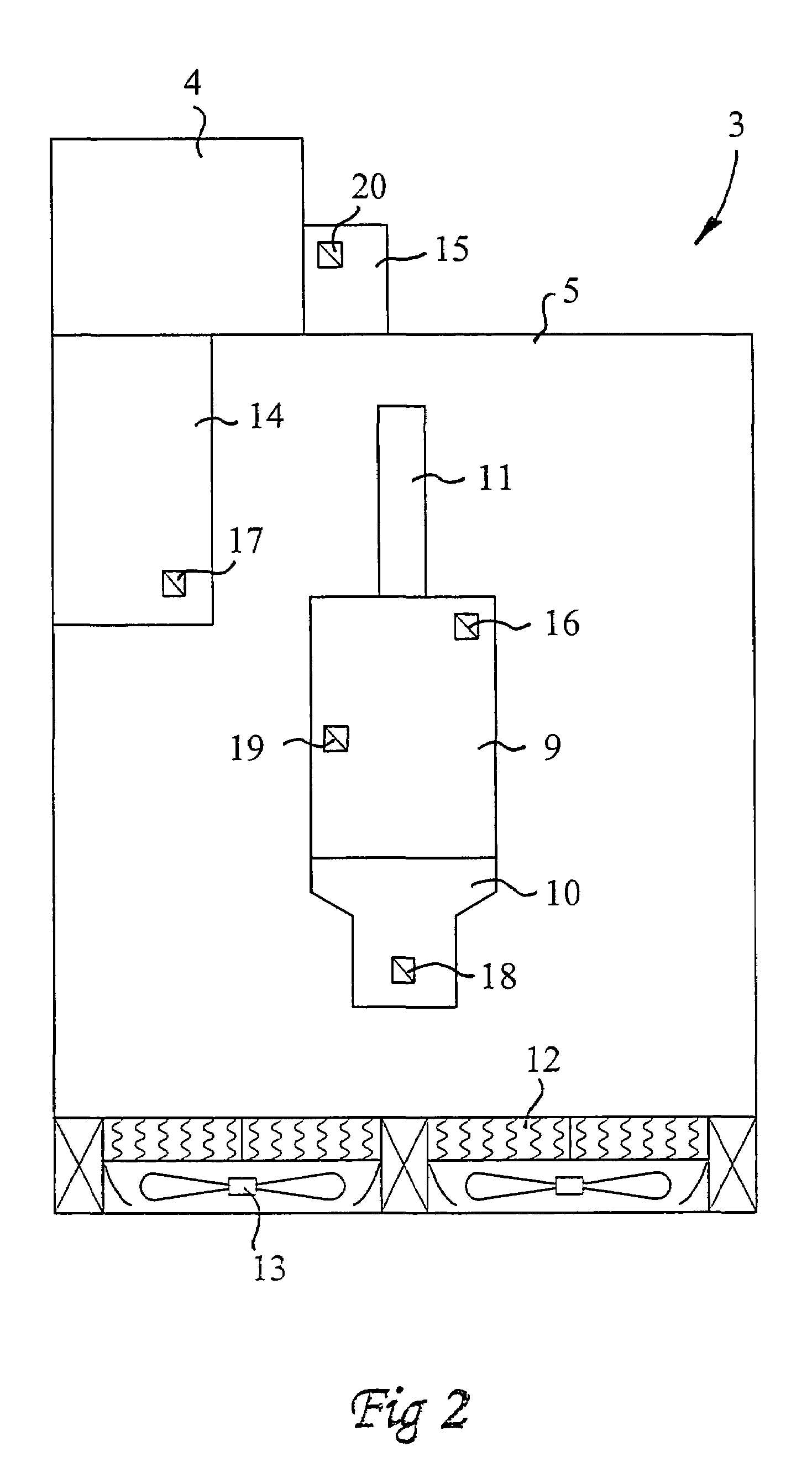
[0018]Now reference is made primarily to FIG. 2, in which a partially cut view from above of the carrier 3 of the drill rig 1 (a plurality of components are eliminated for the sake of clarity) is schematically shown. Centrally in the engine house 5, an engine 9 is arranged, preferably an internal comb...


PUM


Abstract

In a method for controlling at least one fan (13) for the regulation of the cooling demand of at least two cooling elements (12) included in a drill rig (1), the cooling demand of each one of the cooling elements (12) being determined, that the determined cooling demands are weighted together and that the fan (13) is controlled based on the weighting together. At least one cooling element is equipped with a safety thermostat, which, if required, prevents undercooling by the fact that the fluid in question is not allowed to circulate in this cooling element. Also described is a drill rig for the execution of the above-mentioned method.

Description

TECHNICAL FIELD OF THE INVENTION[0001]This invention relates to a method for controlling at least one fan for the regulation of the cooling demand of at least two cooling elements comprised in a drill rig, the cooling demand of each one of the cooling elements being determined, that the determined cooling demands are weighted together and that the fan is controlled based on said weighting together.[0002]The invention also relates to a drill rig comprising an engine, at least two cooling elements and at least one fan, a control unit being arranged to control the fan based on a weighting together, executed in the control unit, of current cooling demands in the cooling elements.[0003]By drill rigs, in particular drill rigs for drilling in rock are intended and above all drill rigs for drilling in rock above ground.BACKGROUND OF THE INVENTION AND PRIOR ART[0004]The background of the present invention is the need of being able to provide cooling in a drill rig, or in a drilling unit, whi...

Claims


Application Information

Patent Timeline
Patent Type & Authority Patents(United States)
IPC IPC(8): F01P7/16
CPCF01P5/02F01P7/04F01P2005/025F01P2023/00F01P2060/045F01P2025/13F01P2060/02F01P2060/04F01P2023/08
Inventor JACOBSSON, HENRIK
Owner EPIROC ROCK DRILLS AB
Learn More