
Keypad assembly and portable electronic device with same

a technology of keypad and assembly, applied in the field of key assemblies, can solve the problems of reducing the strength of the keypad assembly and making the keypad assembly b>100/b> more susceptible to breakag

Inactive Publication Date: 2008-07-01
CHI MEI COMM SYST INC
View PDF10 Cites 54 Cited by
  • Summary
  • Abstract
  • Description
  • Claims
  • Application Information

AI Technical Summary

Benefits of technology

The patent describes a keypad assembly for a portable electronic device. It includes a base with a fixing portion and a latching slot, and a key fixed on the base. The assembly also has an elastic member with latching portions that fit into the latching slot and a rib that fits into the slot. The technical effect of this design is to securely hold the key in place and prevent it from moving or falling off during use.

Problems solved by technology

This thickness reduction would, however, likely decrease the strength of the keypad assembly 100 and thus make the keypad assembly 100 more susceptible to breakage.

Method used


Image

  • Keypad assembly and portable electronic device with same
  • Keypad assembly and portable electronic device with same
  • Keypad assembly and portable electronic device with same

Examples


first embodiment

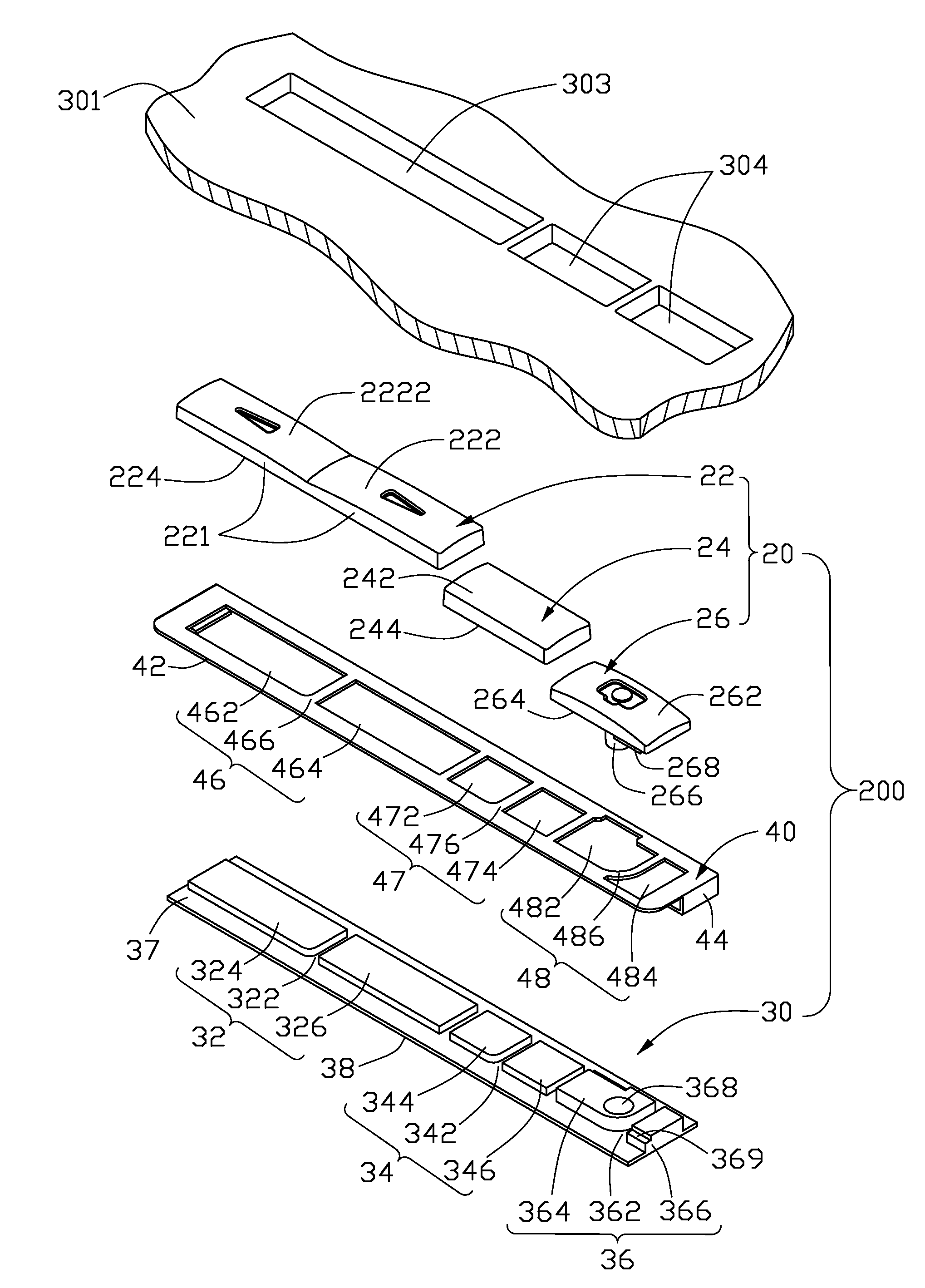
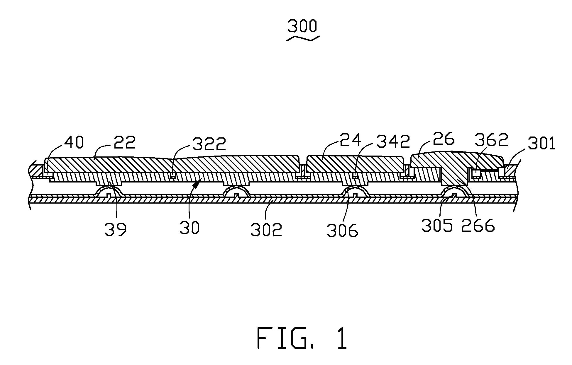
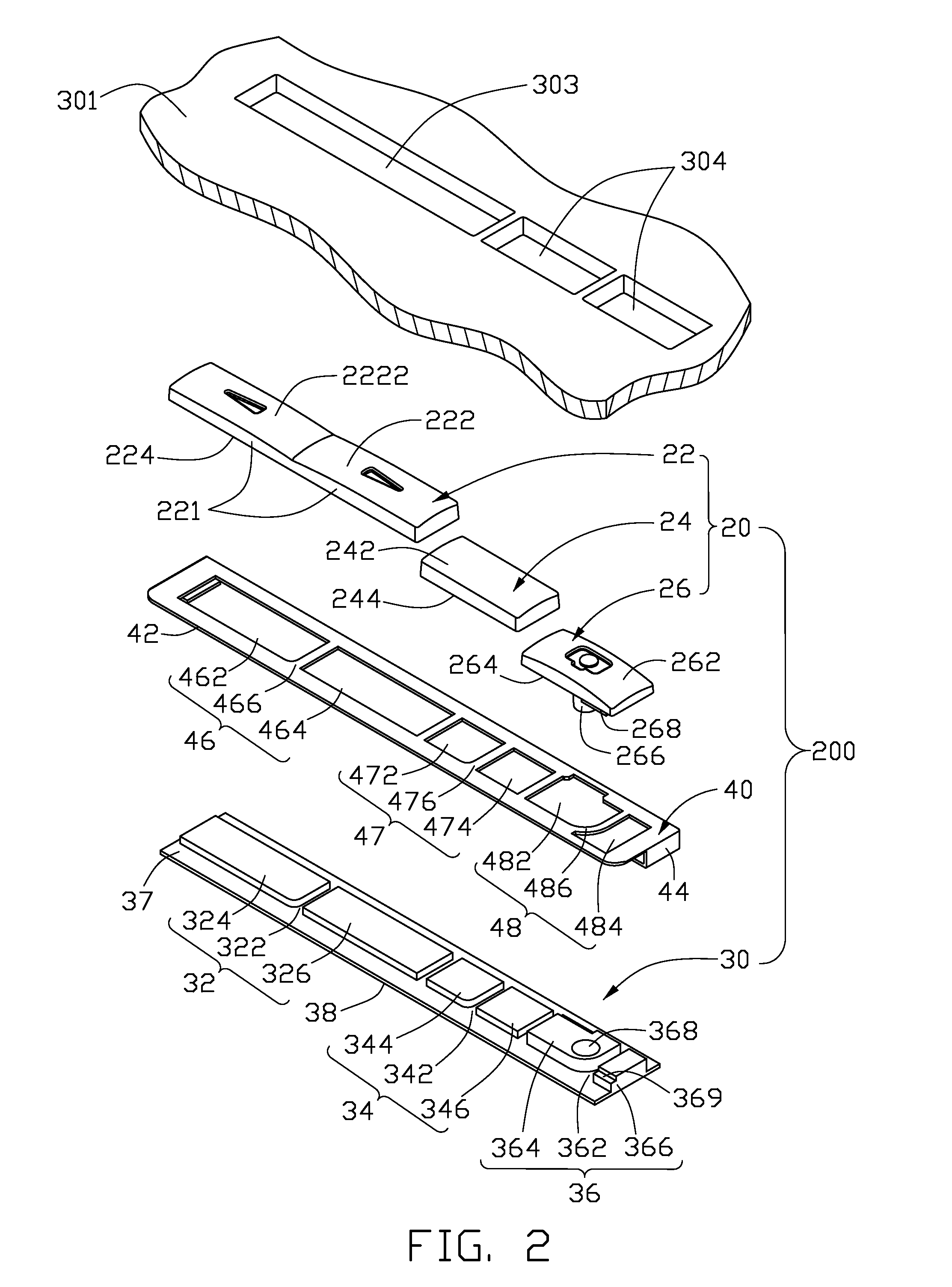
[0020]Referring to FIGS. 1 and 2, a keypad assembly 200 is used in a portable electronic device 300, according to present invention. The portable electronic device 300 includes, in addition to the keypad assembly 200, a shell 301 and a printed circuit board 302 received in the shell 301. A large receiving hole 303 and two small receiving holes 304 are defined in the shell 301. Such receiving holes 303, 304 are spaced and distinct from one another and are aligned in an essentially linear formation. Further, the receiving holes 303, 304, are generally rectangular and extend through the shell 301. The printed circuit board 302 has four fixed contact points 305 formed thereon. Four dome switches 306 are respectively disposed above each fixed contact point 305. The keypad assembly 200 includes a key group 20, a base 30, and an elastic member 40. The keypad assembly 200 is used to facilitate the selective pressing of a chosen dome switch 306, so as to push the desired fixed contact point ...

second embodiment

[0029]In present invention, referred to FIG. 3, a keypad assembly 500 includes a control key 512, an elastic member 520 and a base 540. The elastic member forms a latching portion 522. The latching portion 522 has three latching apertures 524 and two ribs 526 separating each two adjacent latching apertures 524. The base 540 includes a fixing portion 542. The fixing portion 542 has two latching slots 544 defined therein so as to form three positioning blocks 546 engaged with the latching apertures 524. This structure may increase the bonding force between the elastic member 40 and the base 30 so that the structure of the keypad assembly 200 may be more stable.

third embodiment

[0030]Referring to FIG. 4, in a third embodiment according to present invention, a keypad assembly 600 includes three control keys 612, an elastic member 620 and a base 640. Each control key 612 has two operating surfaces 6122. The elastic member 620 includes three first latching portions 622. Each first latching portion 622 has two latching apertures 624 and a rid 626 separating the two latching apertures 624. The base 640 includes three first fixing portions 642 engaged with the latching portions 622 respectively. Each first fixing portion 642 has two positioning blocks 644 and a latching slot 646 between the two positioning blocks 644. Each of the operating surfaces 6122 of the control key 612 corresponds to a cylindrical projection 39 extending from the lower surface 38 of the base 30.


PUM


Abstract

A keypad assembly (200) applied to a portable electronic device (300) includes at least one key (24), a base (30) and an elastic member (40). The base includes at least one fixing portion (34). The at least one fixing portion is divided into two positioning blocks (344) by means of a latching slot (342). The at least one key is fixed on the at least one fixing portion. The elastic member includes at least one latching portion. Each latching portion includes two latching apertures and a rib. Each positioning block is engaged in a corresponding latching aperture. Each rib is received in a corresponding latching slot.

Description

BACKGROUND OF THE INVENTION[0001]1. Field of the Invention[0002]The present invention generally relates to key assemblies and, particularly, to a keypad assembly applied to a portable electronic device, such as mobile telephone, electronic notebook, and a portable electronic device with the same.[0003]2. Description of Related Art[0004]With the development of wireless communication and information processing technologies, portable electronic devices, such as mobile telephones and personal digital assistants (PDAs), are now in widespread use. These portable electronic devices enable consumers to enjoy high technology services, anytime and anywhere. A keypad assembly as an input terminal has been an indispensable member of a portable electronic device.[0005]A typical keypad assembly is used for a portable electronic device including a printed circuit board therein. Several fixed contact points are formed on the printed circuit board and several dome switches respectively disposed abov...

Claims


Application Information

Patent Timeline
Patent Type & Authority Patents(United States)
IPC IPC(8): H01H13/70
CPCG06F3/0202H01H13/705H01H2221/016H01H2233/04H01H2223/056H01H2227/036H01H2223/034
Inventor CHANG, MING-SHIUNG
Owner CHI MEI COMM SYST INC
Learn More