
Electronic musical apparatus system, server-side electronic musical apparatus and client-side electronic musical apparatus

a musical instrument and server-side technology, applied in the field of electronic musical instrument systems, can solve the problems that the musical instruments cannot be operated independently and concurrently

Active Publication Date: 2008-06-24
YAMAHA CORP
View PDF46 Cites 6 Cited by
  • Summary
  • Abstract
  • Description
  • Claims
  • Application Information

AI Technical Summary

Benefits of technology

The present invention provides an electronic musical apparatus system that allows multiple electronic musical apparatuses to independently and concurrently perform sophisticated and high-performance tasks. This is achieved through a communications network, where each client-side electronic musical apparatus has its own unique identification data that is attached to operational signals transmitted from other client-side electronic musical apparatuses. The server-side electronic musical apparatus performs various processing independently and concurrently in response to requests from the plurality of client-side electronic musical apparatuses. This allows the client-side electronic musical apparatuses to utilize the sophisticated and high-performance functions of the server-side electronic musical apparatus, even if they are simple and low-performance. The invention can be embodied as a computer program and method.

Problems solved by technology

In the above conventional scheme, however, those apparatuses cannot be operated independently and concurrently.

Method used


Image

  • Electronic musical apparatus system, server-side electronic musical apparatus and client-side electronic musical apparatus
  • Electronic musical apparatus system, server-side electronic musical apparatus and client-side electronic musical apparatus
  • Electronic musical apparatus system, server-side electronic musical apparatus and client-side electronic musical apparatus

Examples


Embodiment Construction

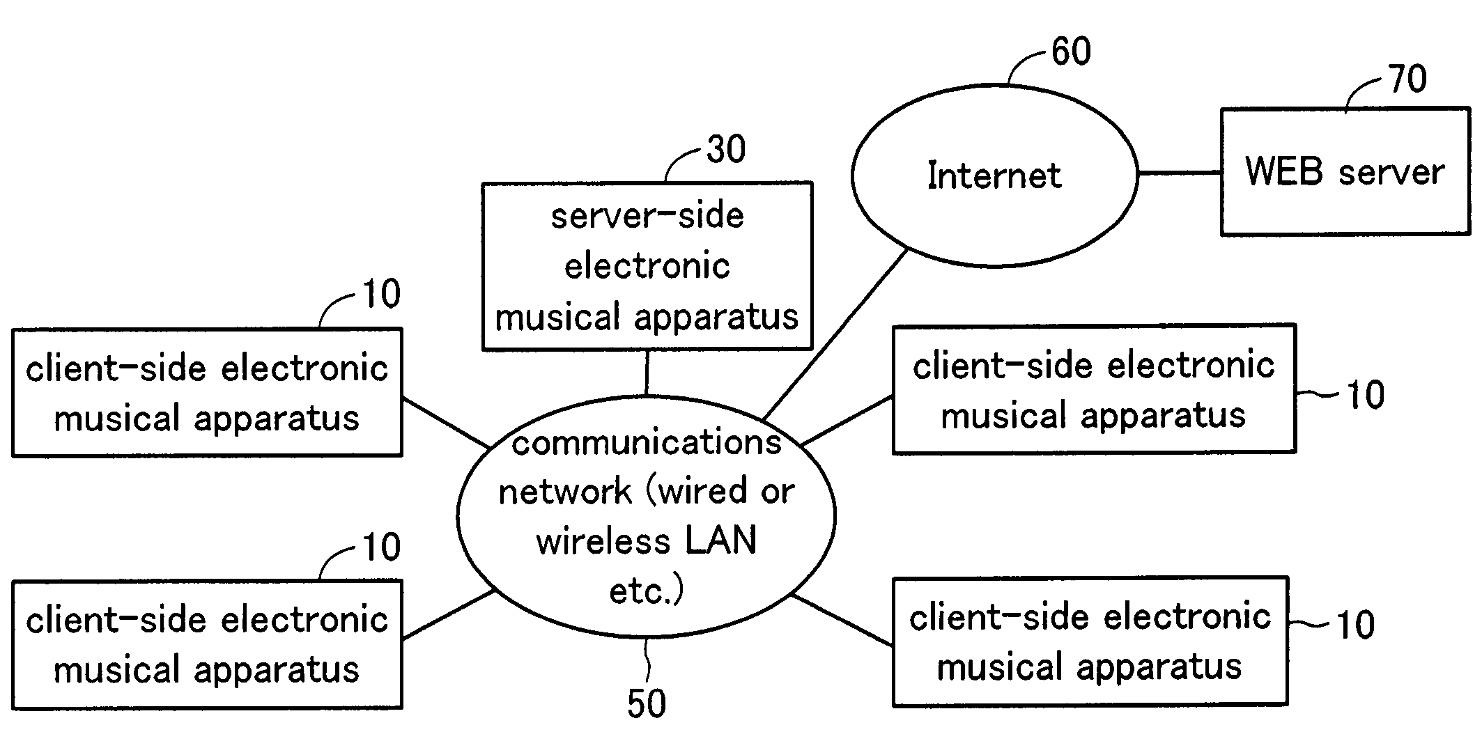
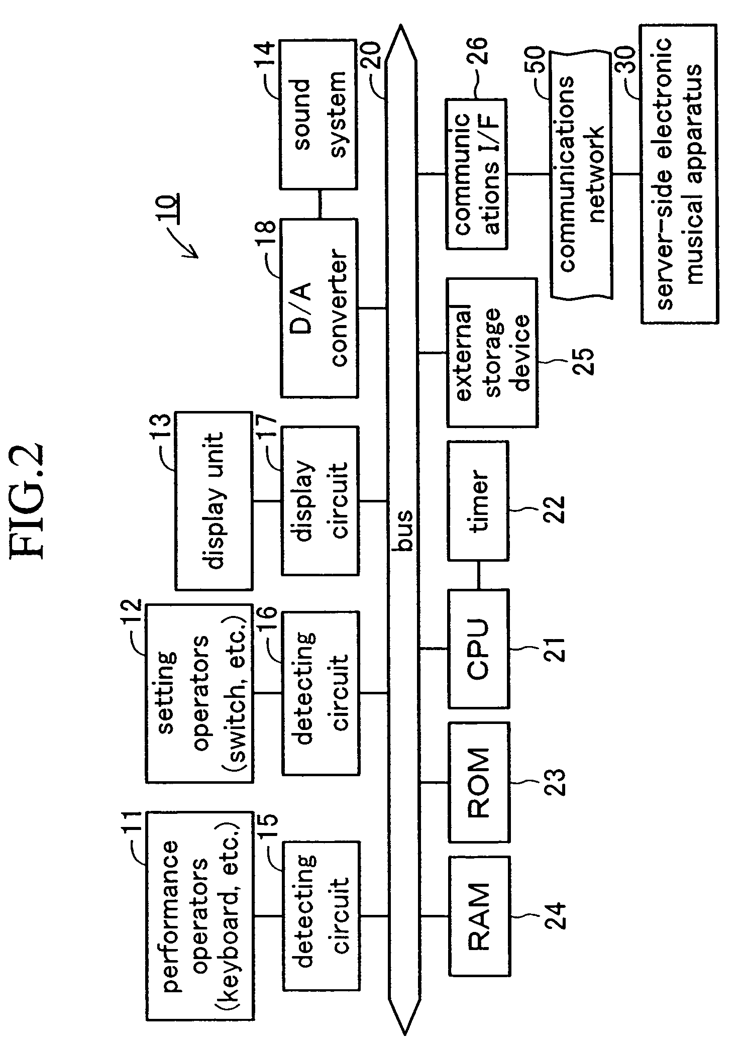
[0018]An embodiment of the present invention will now be described with reference to the drawings. FIG. 1 shows a block diagram showing an electronic musical apparatus system of the present invention. The electronic musical apparatus system includes a plurality of client-side electronic musical apparatuses 10 (four client-side electronic musical apparatuses 10 in the present embodiment) and a server-side electronic musical apparatus 30. The client-side electronic musical apparatuses 10 and the server-side electronic musical apparatus 30 are located in a relatively confined area such as a music room, a music rehearsal room or a building, interconnecting via a communications network 50 such as a wired or wireless local network. The communications network 50 is also connected to the Internet 60 to allow the server-side electronic musical apparatus 30 and the client-side electronic musical apparatuses 10 to download various programs and data from a WEB server 70 via the Internet 60.

[001...


PUM


Abstract

A plurality of client-side electronic musical apparatuses 10 are connected to a server-side electronic musical apparatus 30 through a communications network 50. Each of the client-side electronic musical apparatuses 10, which is provided with an ID, attaches the ID to a signal representative of operation of performance operators 11 and setting operators 12, and transmits the ID-added signal to the server-side electronic musical apparatus 30. The server-side electronic musical apparatus 30 independently and concurrently executes, through the use of the ID, processes corresponding to the operational signals for the respective client-side electronic musical apparatuses 10 to generate musical tone data and display data, and transmits the generated data with the ID to the respective client-side electronic musical apparatuses 10. The thus-transmitted data is appropriately received by the client-side electronic musical apparatus 10 identified on the basis of the ID. In spite of having a simple configuration, therefore, the respective client-side electronic musical apparatuses 10 are able to independently and concurrently operate as a sophisticated and high-performance electronic musical apparatus.

Description

BACKGROUND OF THE INVENTION[0001]1. Field of the Invention[0002]The present invention relates to an electronic musical apparatus system in which a plurality of client-side electronic musical apparatuses are connected to a server-side electronic musical apparatus via a communications network, the server-side electronic musical apparatus and the client-side electronic musical apparatuses which compose the system, and computer programs applied to the apparatuses.[0003]2. Description of the Related Art[0004]There have been a wide variety of electronic musical apparatuses such as electronic musical instruments, ranging from sophisticated and high-performance apparatuses (hereinafter referred to as high-grade apparatuses) to unsophisticated and low-performance apparatuses (hereinafter referred to as low-grade apparatuses). In addition, there has been a conventional scheme in which a low-grade apparatus is connected with a high-grade apparatus through MIDI, for example, to allow the low-gr...

Claims


Application Information

Patent Timeline
Patent Type & Authority Patents(United States)
IPC IPC(8): G10H7/00
CPCG10H1/0066G10H2220/005G10H2240/115
Inventor MIZUNO, SHIGEHIKO
Owner YAMAHA CORP
Learn More