
Multicolour chromaticity sensor

a chromaticity sensor and multi-colour technology, applied in the field of optical sensing devices, can solve the problems of affecting the chromaticity of light, the spectral responsivities of commercial tristimulus colour sensors such as those manufactured by hamamatsuTM and taosTM can only approximate the cie colour matching function in a reasonable way, and the change in the output of tristimulus colour sensors, so as to determine the intensity and chromaticity

Inactive Publication Date: 2008-06-17
KONINK PHILIPS ELECTRONICS NV
View PDF24 Cites 30 Cited by
  • Summary
  • Abstract
  • Description
  • Claims
  • Application Information

AI Technical Summary

Benefits of technology

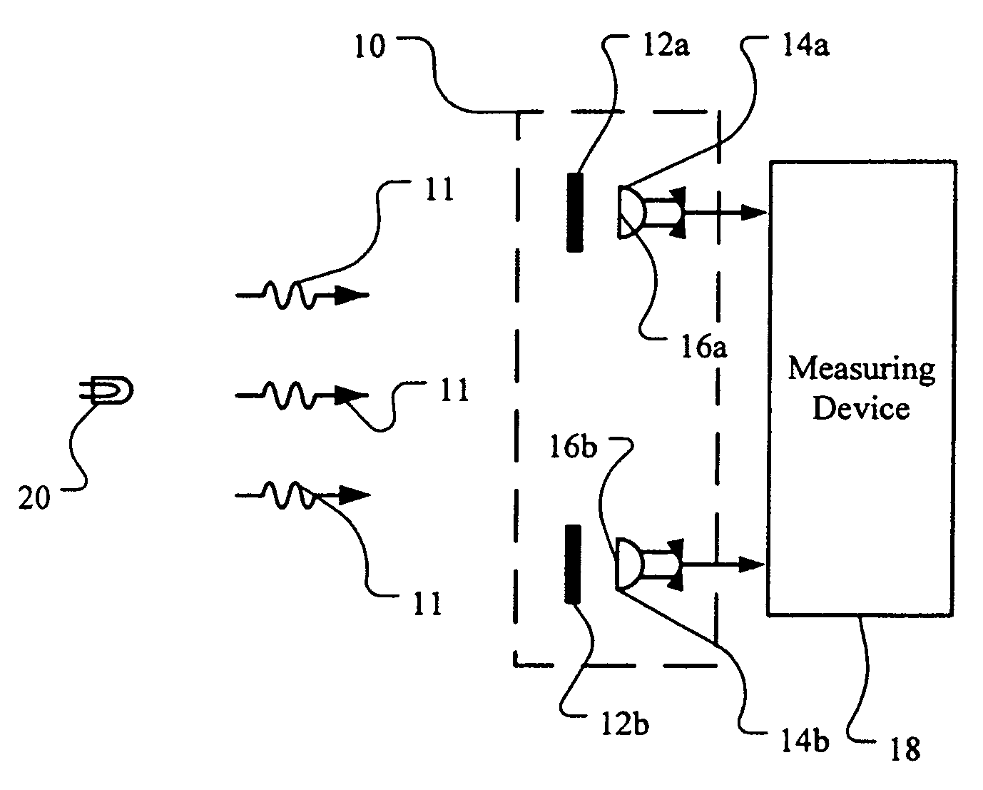
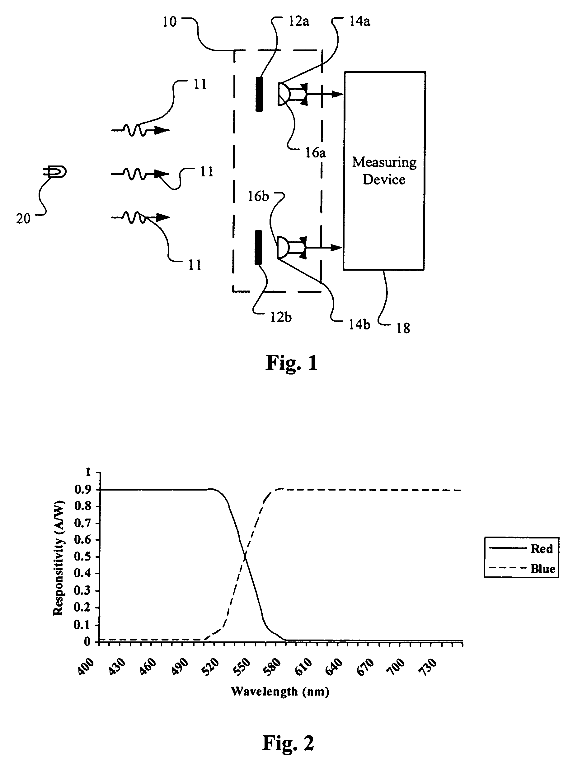
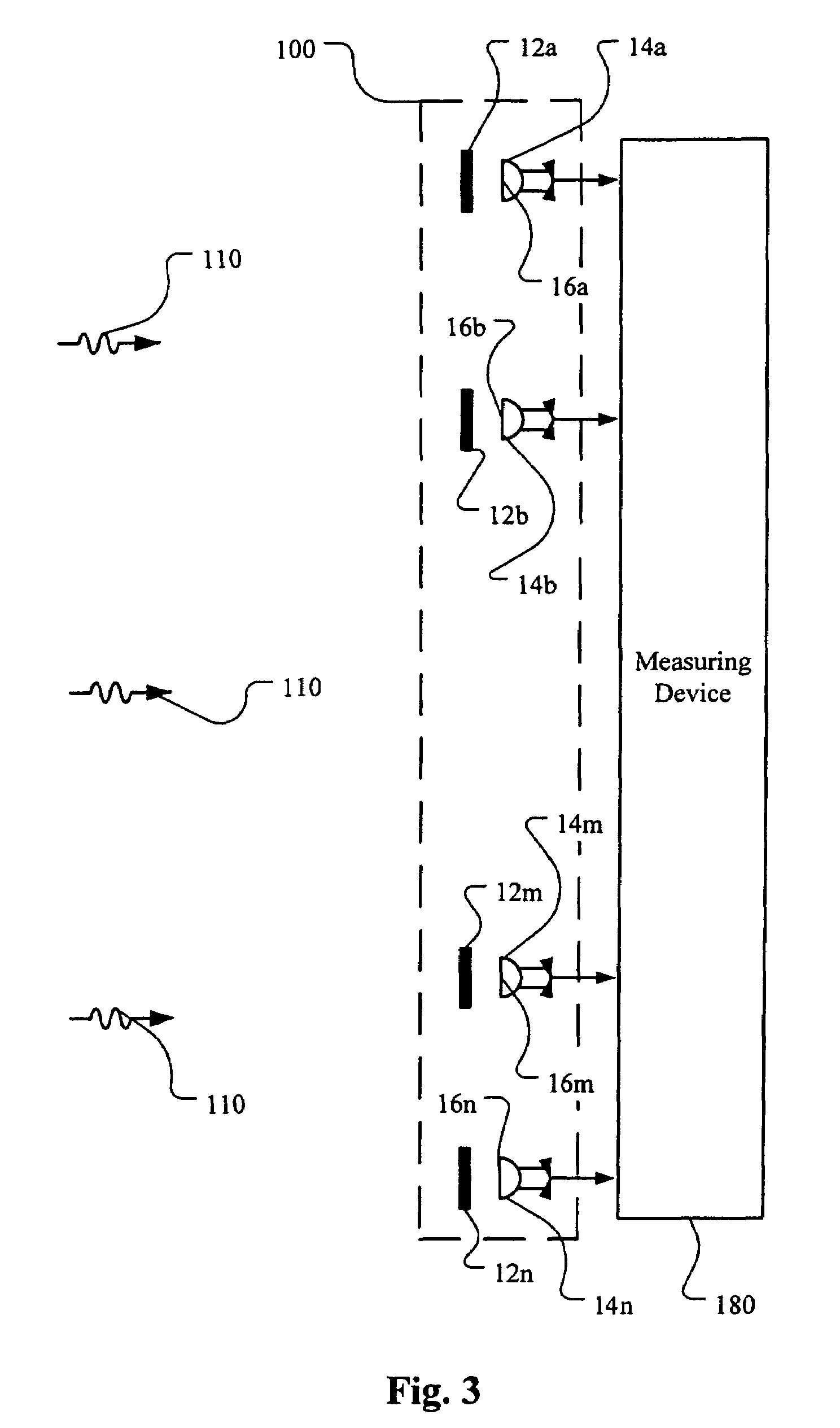
The present invention provides a multicolour chromaticity sensor that can determine the intensity and chromaticity of light. The sensor includes two or more photodetectors that generate sensor parameters for the light incident upon their detection zones. The sensor also includes two or more filters, one filter optically coupled to each photodetector, to form a complementary pair. A measuring means receives the sensor parameters from each photodetector and determines the intensity and chromaticity of the light. The invention also provides an illumination system that includes multiple light-emitting elements and sensors for measuring the intensity and chromaticity of the light. The system can control the intensity of light emission of each light-emitting element based on the sensor signals.

Problems solved by technology

While it can be difficult and expensive to manufacture suitable filter-photodetector combinations to approximate the colour matching functions of the human visual system, tristimulus colour sensors may be used to directly measure white light intensity and chromaticity.
In practice, however, the spectral responsivities of commercial tristimulus colour sensors such as those manufactured by Hamamatsu™ and TAOS™ can only roughly approximate the CIE colour matching functions.
Third, even if the spectral power distributions of the colour LEDs and the spectral responsivities of the filter-photodetector combinations of the tristimulus colour sensor do not overlap, any change in the dominant wavelengths of the light produced by the LEDs can result in changes in the tristimulus sensor output.
If the LEDs' spectral power distributions themselves overlap, for example as occurs with red and amber LEDs, optical crosstalk will be unavoidable with tristimulus colour sensors.
However, most spectroradiometer designs require precision optics and a considerable volume of space that is incompatible with microelectronic subsystems.
Moreover, most of the existing spectroradiometer designs are typically difficult to fabricate, especially those based on micromachined moving parts.
The spectroradiometer approach fails in that such devices are generally complex and expensive to manufacture, and they generate an overabundance of data that must be analyzed to obtain a few significant values, for example LED intensity and dominant wavelength.
A disadvantage of the photodiode design disclosed by Carr is that it can be difficult to obtain predetermined and desirable spectral responsivities solely through the use of semiconductor manufacturing techniques.
As a result, the spectral resolution of Carr's photodiodes may be poor, particularly in the presence of electrical noise.

Method used


Image

  • Multicolour chromaticity sensor
  • Multicolour chromaticity sensor
  • Multicolour chromaticity sensor

Examples


Embodiment Construction

Definitions

[0024]The term “light-emitting element” is used to define any device that emits radiation in any region or combination of regions of the electromagnetic spectrum for example, the visible region, infrared and / or ultraviolet region, when activated by applying a potential difference across it or passing a current through it, for example. Therefore a light-emitting element can have monochromatic, quasi-monochromatic, polychromatic or broadband spectral emission characteristics. Examples of light-emitting elements include semiconductor, organic, or polymer / polymeric light-emitting diodes, optically pumped phosphor coated light-emitting diodes, optically pumped nano-crystal light-emitting diodes or any other similar light-emitting devices as would be readily understood by a worker skilled in the art. Furthermore, the term light-emitting element is used to define the specific device that emits the radiation, for example a LED die, and can equally be used to define a combination ...


PUM

PropertyMeasurementUnit
CIE colour rendering indexaaaaaaaaaa
wavelength rangeaaaaaaaaaa

Abstract

The present invention provides an optical sensor having one or more filter-photodetector pairs and feedback to monitor the intensity and chromaticity of the white light generated by an illumination system. According to the present invention, filter-photodetectors are configured into pairs thereof, wherein a first filter-photodetector of a pair is configured and arranged so as to be sensitive to a predetermined region of the electromagnetic spectrum, while a second filter-photodetector of the pair is configured and arranged to be sensitive to a substantially complementary region of the electromagnetic spectrum. The spectral responsivity of the first filter-photodetector and the second filter-photodetector overlap in a predetermined region of the electromagnetic spectrum. Furthermore, the spectral responsivity of the first filter-photodetector is configured to substantially monotonically increase with respect to wavelength within said predetermined region, while the spectral responsivity of the second filter-photodetector is configured to substantially monotonically decrease with respect to wavelength within said predetermined region.

Description

CROSS REFERENCE TO RELATED APPLICATION[0001]This application claims the benefit of U.S. Provisional Patent Application No. 60 / 683,436, filed May 20, 2005, which is incorporated herein, in its entirety, by reference.FIELD OF THE INVENTION[0002]The present invention relates to optical sensing devices, and more particularly to multicolour chromaticity sensing devices for use with lighting devices.BACKGROUND OF THE INVENTION[0003]Light-emitting diodes (LEDs) are semiconductor devices that convert electrical energy directly into visible light of various colours. With the advent of high-flux LEDs, luminaires are progressively being moved from the traditional incandescent or fluorescent lamps to LEDs for increased reliability, higher luminous efficacy and lower maintenance costs. LED-based luminaires are increasingly becoming the architecture of choice in a variety of mainstream commercial applications such as accent lights, wall washing, signage, advertising, decorative and display lighti...

Claims


Application Information

Patent Timeline
Patent Type & Authority Patents(United States)
IPC IPC(8): G01N21/25G01J3/50
CPCG01J3/10G01J3/51G01J3/513
Inventor ASHDOWN, IAN
Owner KONINK PHILIPS ELECTRONICS NV
Learn More