
High intensity discharge lamp control

a high-intensity discharge and lamp technology, applied in the direction of electrical variable regulation, sustainable buildings, instruments, etc., can solve the problems of lamp over- or under-driven, electrode damage, and inability to control the output voltage of the lamp, so as to improve the operation of the lamp, stable power operation, and stable light output

Inactive Publication Date: 2008-06-10
THE ACTIVE REACTOR
View PDF13 Cites 36 Cited by
  • Summary
  • Abstract
  • Description
  • Claims
  • Application Information

AI Technical Summary

Benefits of technology

"The present invention provides a controller for a high intensity discharge lamp that includes a primary ballast for electrical connection between a power supply and the lamp, a current injector for injecting a secondary current to the lamp, and a control unit for monitoring and adjusting the current. The controller uses a fixed primary ballast and a variable secondary current to control the overall power of the lamp. The control unit monitors various parameters of the lamp and power supply and adjusts the secondary current accordingly to maintain a stable power level. The current injector can be a switched-mode power supply or a control ballast. The controller allows for intelligent control of the lamp power and can compensate for changes in the power supply or lamp characteristics. The current injector can be connected at various points in the circuit, such as between the primary ballast and the lamp. The control unit can also monitor and adjust the voltage across the ballast to ensure synchronization with the secondary current. The ratio of the primary current to secondary current can be adjusted to compensate for changes in the lamp or power supply. Overall, the controller provides a practical and efficient solution for controlling the power of a high intensity discharge lamp."

Problems solved by technology

In practical installations, however, the input supply voltage can change due to supply line disturbances and the like, and this can result in a lamp being over-driven or under-driven.
If a lamp is over-driven, it can exhibit adverse characteristics such as overheating, reduction in lamp life, electrode damage, reduced efficiency and low colour temperature.
Conversely, if a lamp is under-driven, adverse characteristics of low light output, reduced efficiency, high colour temperature and arc tube blackening tend to result.

Method used


Image

  • High intensity discharge lamp control
  • High intensity discharge lamp control
  • High intensity discharge lamp control

Examples


Embodiment Construction

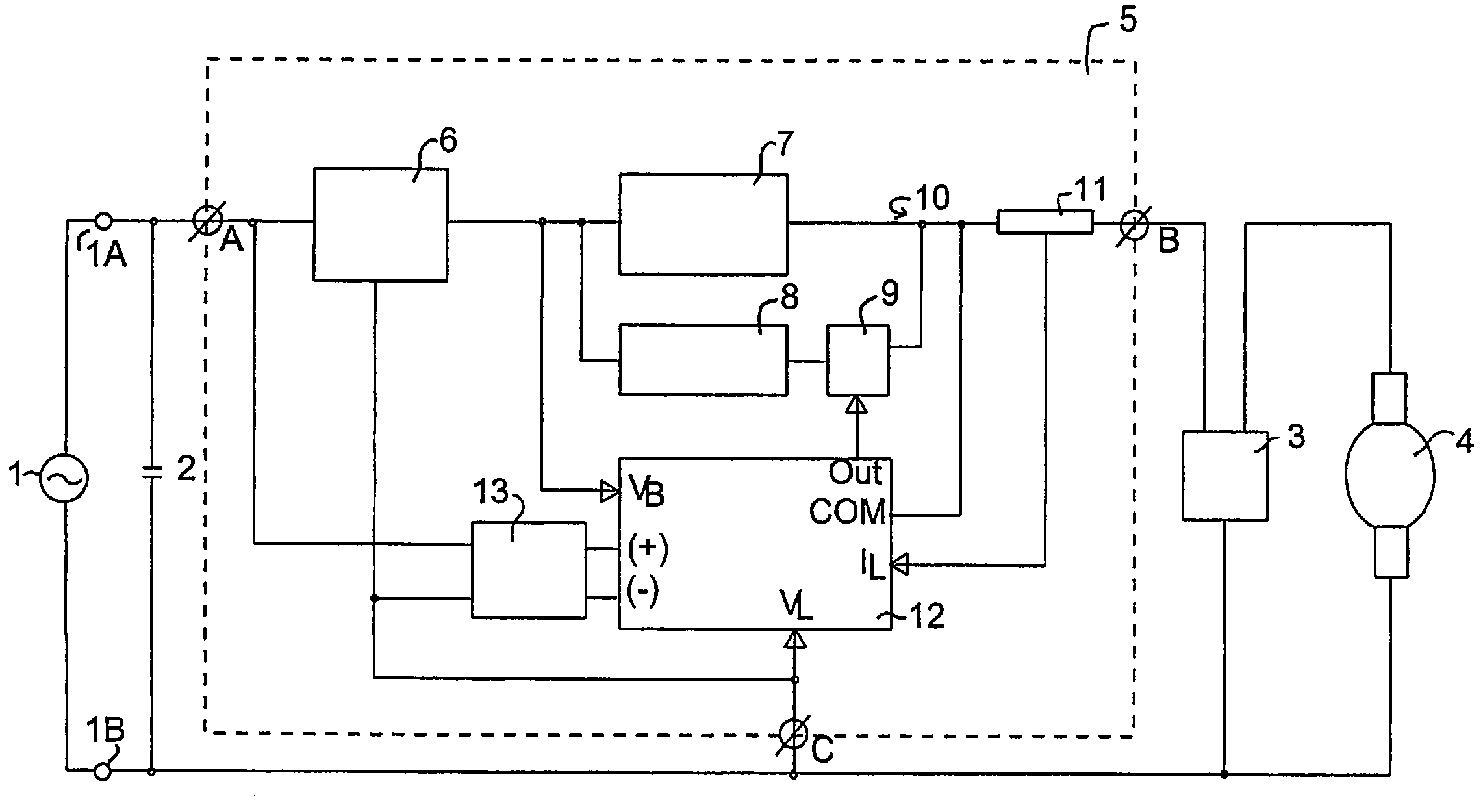
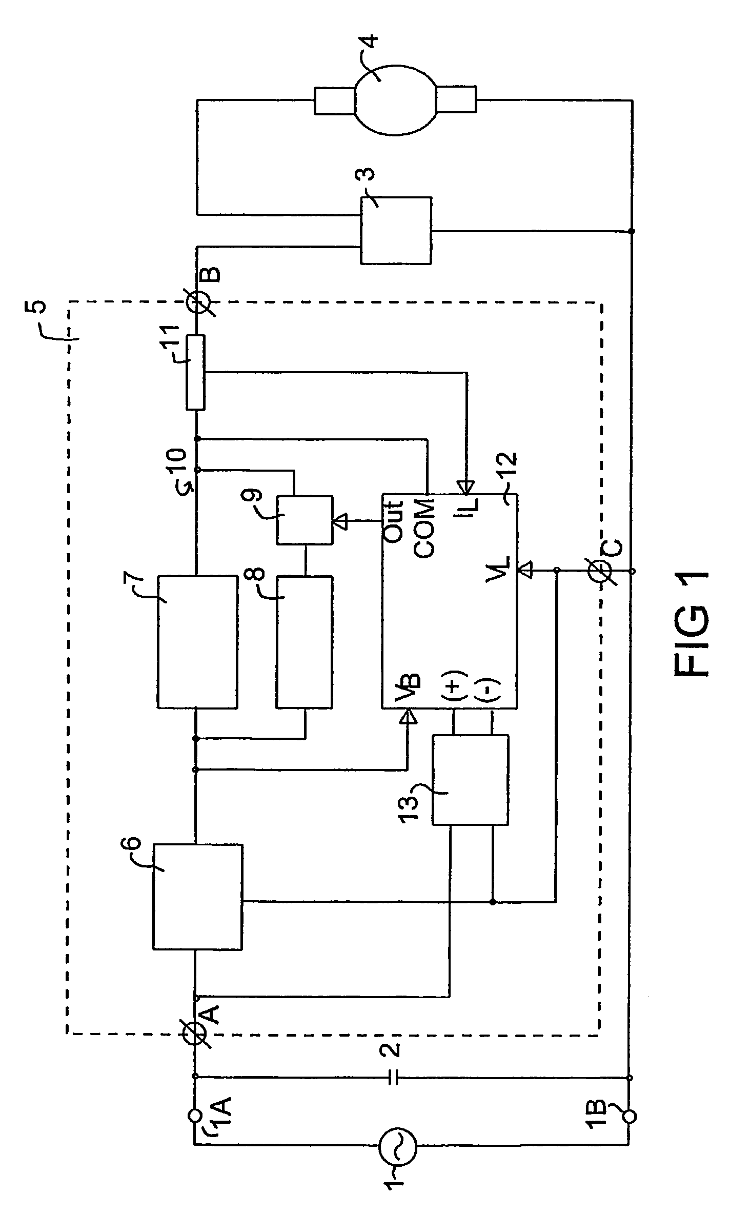
[0077]Referring to FIG. 1, this shows a schematic block diagram of the arrangement of components of a lighting system configured according to one embodiment of the present invention.

[0078]The circuit includes an a.c. power source 1, having terminals 1A and 1B, connected to a lamp controller 5 which is placed in circuit with an ignitor 3 and an HID lamp 4. The ignitor 3 may be any conventional ignitor that is suitable for the initial starting of an HID lamp, preferably the ignitor 3 is an electronic ignitor. The lamp 4 may be any suitable HID lamp. Although any suitable HID lamp may be controlled by the present invention, the invention is particularly suitable for controlling high pressure sodium, metal halide or mercury vapour discharge lamps, and for controlling lamps with a power rating between about 150 watts and about 2000 watts, e.g. lamps rated at greater than or equal to about 250 watts, 400 watts, or 1000 watts. The circuit also includes a power factor correction capacitor 2...


PUM


Abstract

A controller 5 for a high intensity discharge lamp 4 includes a primary ballast for providing a primary current to the lamp 4, and a current injector which in the case shown comprises a control ballast 8 and a switch 9 (e.g. a triac) controlled by a control unit 12. The current injector injects a secondary current into the lamp 4 that is less than the primary current and can be varied by the control unit 12, e.g. by varying the amount of time within an a.c. cycle that the control ballast 8 is switched into the circuit. The controller 5 allows the lamp 4 to be controlled, for example, to operate at a constant power (variable light output) or at a constant light output (variable power).

Description

RELATED APPLICATIONS[0001]This invention is related to and claims priority from Australian Patent Application No. 2003902210, filed May 8, 2003, entitled High Intensity Discharge Lamp Control; and PCT Application No. PCT / AU2004 / 000601, filed May 7, 2004, entitled High Intensity Discharge Lamp Control, which are incorporated herein by reference.FIELD OF THE INVENTION[0002]The present invention broadly relates to controllers and circuits for controlling the operation of high intensity discharge lamps. It also broadly relates to methods of controlling the operation of high intensity discharge lamps.BACKGROUND[0003]High intensity discharge (HID) lamps include high pressure sodium lamps, metal halide lamps and mercury vapour lamps. They are distinct from for example fluorescent lamps. For example, they tend to operate under higher pressures and temperatures, they emit visible light directly (although they may also include some phosphor coatings), and they are generally compact light sour...

Claims


Application Information

Patent Timeline
Patent Type & Authority Patents(United States)
IPC IPC(8): H05B41/36H05B37/00H05B41/288H05B41/392
CPCH05B41/2885H05B41/3921Y02B20/202Y10S315/07Y02B20/00
Inventor DLUZNIAK, RICHARD
Owner THE ACTIVE REACTOR
Learn More