Continuous motion product transfer system with conveyors

a product transfer system and continuous motion technology, applied in the direction of mechanical conveyors, conveyor parts, packaging foodstuffs, etc., can solve the problems of cracker damage, physical limitations of the reciprocating mechanism, and especially troublesome food industry, and achieve the effect of high speed and higher speed

Inactive Publication Date: 2008-05-27
CARDINAL MACHINE CORP USA
View PDF6 Cites 6 Cited by
  • Summary
  • Abstract
  • Description
  • Claims
  • Application Information

AI Technical Summary

Benefits of technology

[0013]The present invention relates to a high speed method for changing the orientation of groups of product. The groups are initially moving with the longitudinal axis of each group in parallel with the longitudinal axis of other similarly moving groups and at a fixed distance between each group. Each group may be composed of a single entity or be composed of individual members. The method for changing the orientation of product is achieved with continuous motion of both the mechanism that executes the change and the product thereby enabling the change to be made at a higher speed than can be achieved by current state of the art methods discussed above.
[0017]The fixed rail guide that restrains the fourth side of the slug at the open end of the flights is preferably positioned to restrain the slug by contacting the upper half of the slug. With the moving flights acting on a portion of the lower half of the slug and the fixed rail guide acting on the upper half of the slug, it is possible for the flights to travel below the fixed rail without interference. This is particularly important in the event the fixed rail and the moving flights must overlap in order to sufficiently restrain the slug of a particular product. If the product being transported is of such a nature that it needs less precise restraint at the open ends of the flights, then the fixed rail guide can be adjacent to the ends of the passing flights and can restrain the slug either above or below the center line of the slug or both, without concern about interference.
[0022]As a consequence of the vector relationship between the two conveyors, one of the two right angle vector components of the cross conveyor in velocity magnitude (speed) and direction, is intentionally made equal to the vector of the first conveyor in velocity magnitude (speed) and direction. Accordingly, a slug that is transferred to the cross conveyor continues to move with the same velocity in the direction of the first conveyor. As the transferred slug in the cross conveyor is moving with the same velocity in the direction of the first conveyor, the slug is also moving laterally away from the first conveyor. Restated, this means that a slug that is being transferred from the first conveyor to the cross conveyor will see no change in velocity in the direction of the first conveyor while simultaneously moving away from the first conveyor in a direction that includes a vector parallel and a vector perpendicular to the direction of travel of the first conveyor.

Problems solved by technology

This is especially troublesome for the food industry and most specifically for mechanical handlers of cookies, crackers, baked goods and the like that will be automatically wrapped while on edge to create packages.
Problems with existing systems at higher speeds include damage to the crackers caused by an abrupt change in direction of travel and the physical limitations of the reciprocating mechanism that transfers the slugs from the first conveyor to the second conveyor due to the inertial forces involved.
Practically, this results in the slug remaining still for a certain moment of time as they are transferred between the two conveyors.
The rate at which crackers may be moved from a dispensing automated machine to an automated wrapping machine is limited by the brief stopping of the crackers as they change direction.
However, since the downstream wrapping operation is not flawless and for this reason and for other reasons that are not germane, automatic electronic means are usually provided to sometimes slow down or stop the wrapping operation and correspondingly slow or stop the cross and first conveyors as well as the product being fed to the first conveyor.
The narrow window of time available for transfer of slugs associated with the abrupt change in direction of motion of the slug and possibly the normal variation in the size of slugs, results in a high rate of product breakage in existing machinery.

Method used


Image

  • Continuous motion product transfer system with conveyors
  • Continuous motion product transfer system with conveyors
  • Continuous motion product transfer system with conveyors

Examples


Embodiment Construction

[0039]For the purposes of providing and understanding the principles of the present invention, reference will now be made to the embodiment illustrated in the drawings and specification language used to describe the same. Nevertheless, by those skilled in the art, it will be understood that no limitation of the scope of the present invention is thereby intended, and further changes in the illustrated device may be made without deviating from the scope of the present invention.

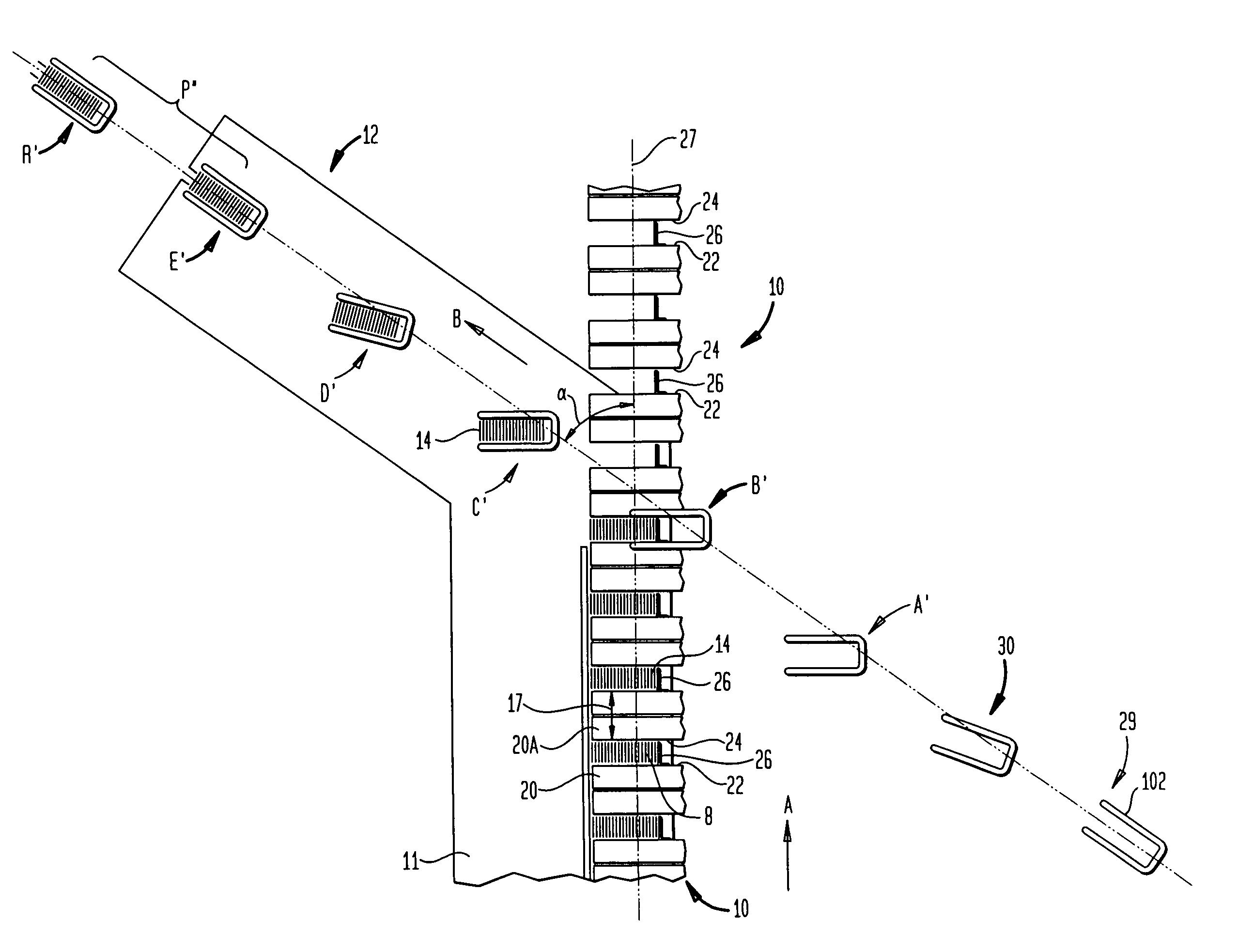
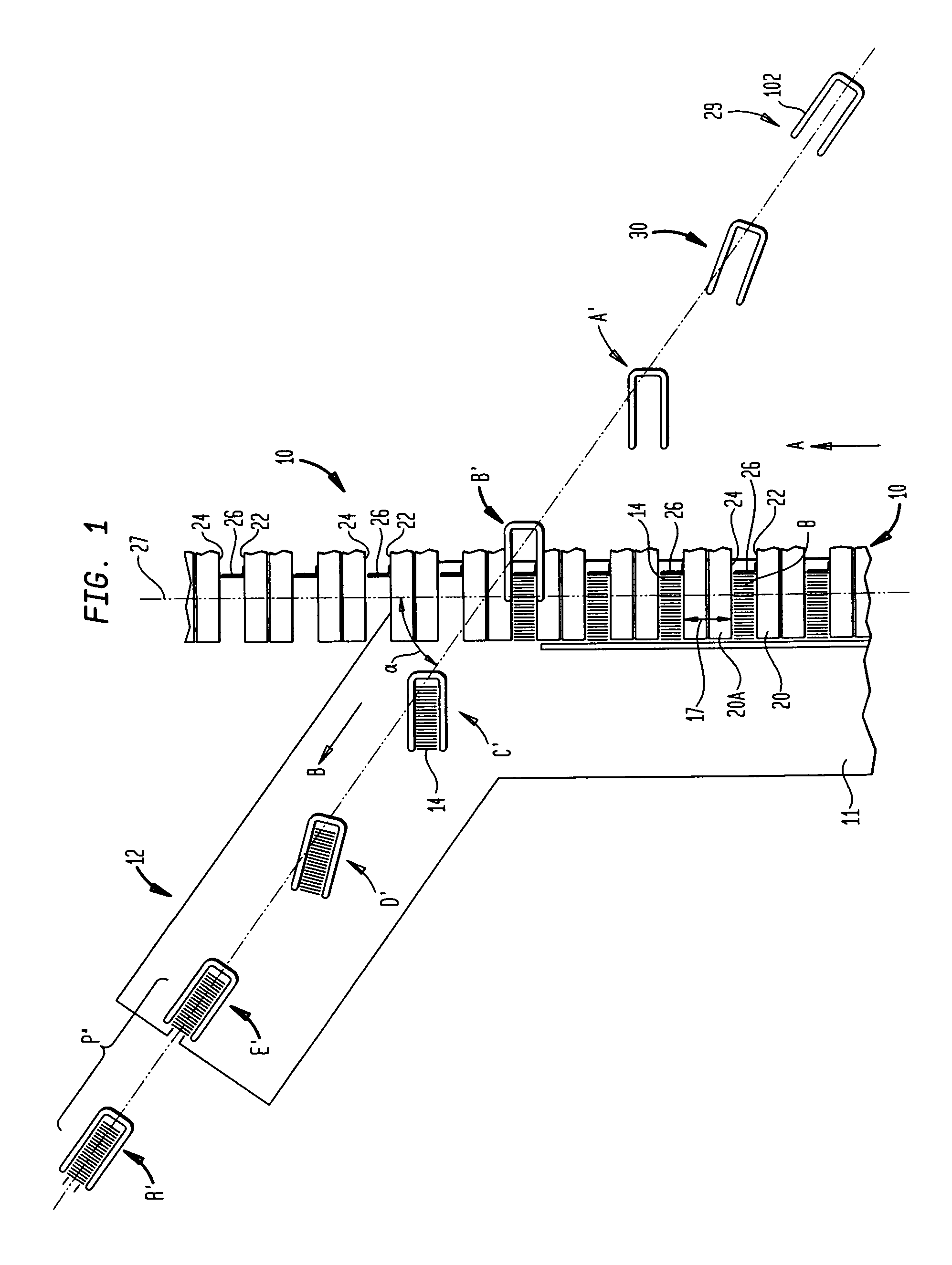
[0040]As shown in FIG. 1, the present invention is designed to transfer product, for instance slugs 14, moving in an X-direction, as indicated by arrow A, along a first conveyor 10 to a cross conveyor 12 moving in a θ-direction indicated by arrow B. The θ-direction consists of an X-coordinate and a Y-coordinate. Although the present invention may be adapted for numerous different products, one preferred embodiment of the present invention relates to transferring baked goods specifically crackers and cookies, kn...


PUM


Abstract

A product transfer system preferably includes a first conveyor for conveying a series of product in a first direction. This system also includes a cross conveyor vertically spaced from the first conveyor and oriented in a second direction angled at an angle α with respect to the first direction. A plurality of rotatable transporters are mounted on the cross conveyor for transferring the product from the first conveyor to the cross conveyor. The transporters are initially oriented perpendicular to the first direction before receiving the products and are rotatable to the second direction after receiving the products.

Description

[0001]This application claims the benefit of U.S. Provisional Application No. 60 / 658,715 filed on Mar. 4, 2005, the disclosure of which is incorporated by reference herein.BACKGROUND OF THE INVENTION[0002]The present invention relates to product transferring systems and more specifically to transferring a discrete number of baked goods such as crackers from a first conveyor to a second conveyor or cross conveyor that is traveling in a generally different direction wherein both the product and the mechanism that conveys the product are in continuous motion.[0003]With today's modern high-speed packaging technology, many products require the rearranging or reorientation of the product as it is being conveyed. This can be due to an automated dispensing machine that initially positions a product with one orientation while a subsequent operation requires that the product be received with a different orientation. This is especially troublesome for the food industry and most specifically fo...

Claims


Application Information

Patent Timeline
Patent Type & Authority Patents(United States)
IPC IPC(8): B65G17/32
CPCB65B23/12B65G47/766B65G47/841B65G2201/0205
Inventor FEIGEL, HAROLDCARDINALI, JOSEPHFEIGEL, DOUGLAS
Owner CARDINAL MACHINE CORP USA
Why Eureka
Try Eureka