
Decentralized energy demand management

a technology of energy demand and decentralized energy, applied in the direction of electric controllers, instruments, ignition automatic control, etc., to achieve the effect of reducing costs

Active Publication Date: 2008-05-13
ROCKWELL AUTOMATION TECH
View PDF13 Cites 221 Cited by
  • Summary
  • Abstract
  • Description
  • Claims
  • Application Information

AI Technical Summary

Benefits of technology

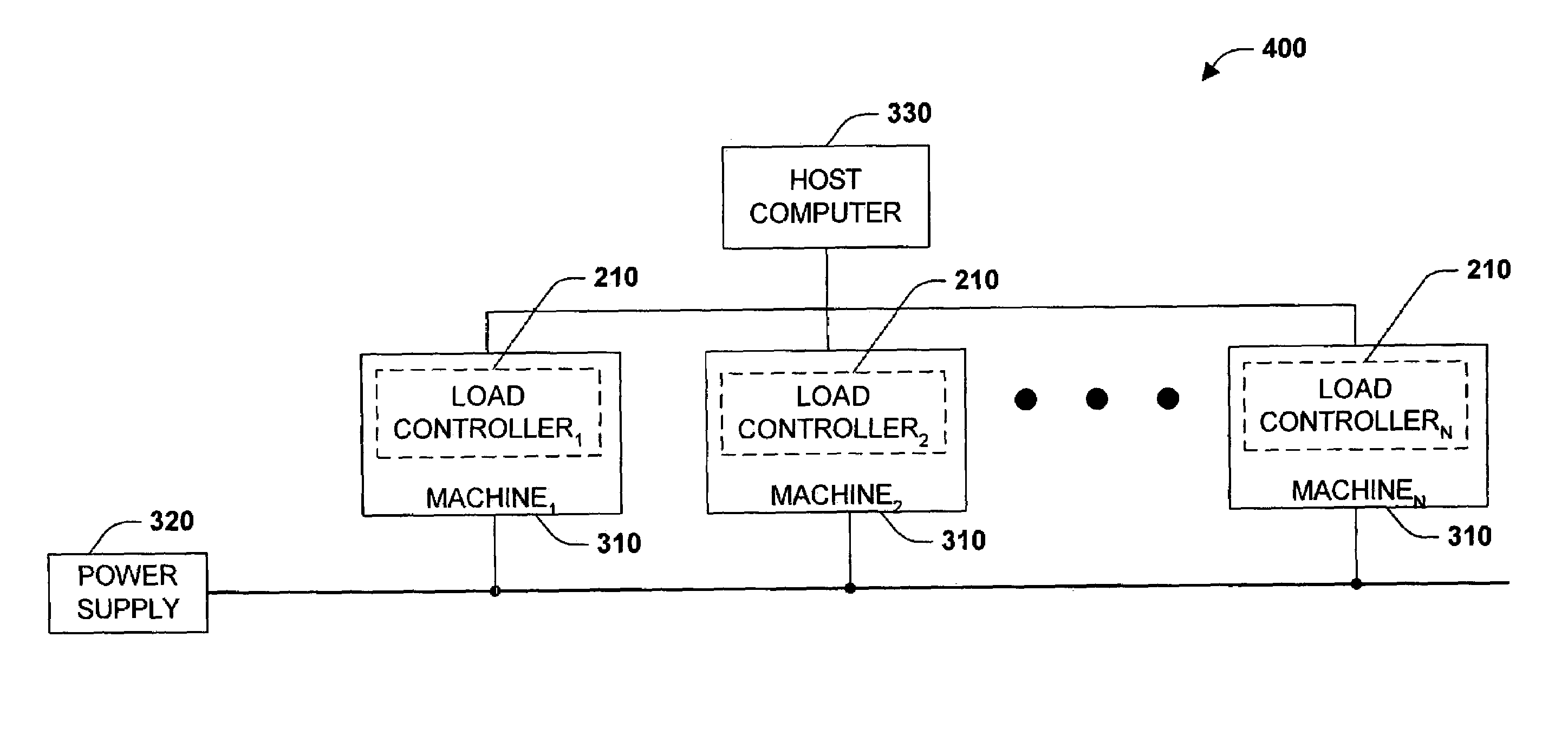
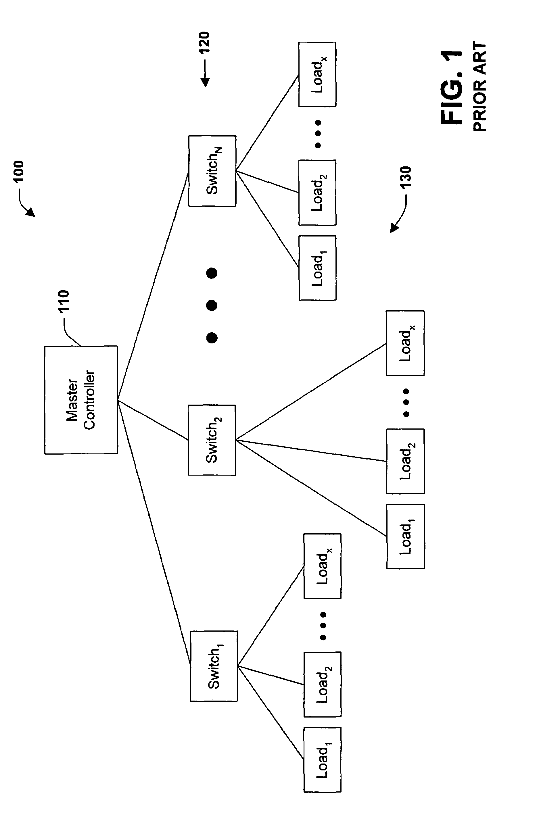
[0008]The subject invention enjoys many benefits and advantages over conventional load control systems and methods. First, there is no single machine that is clearly the master controller, rather individual load controllers share data and collaborate to determine overall system control. Accordingly, cost is reduced because a master controller does not have to be purchased. Furthermore, because the controllers are networked the system is scalable. In a traditional master slave configuration, the breadth of slave devices is needed to be known when the master is selected. According to the present invention, any number of peer devices may be added to the network at any time. Load shedding can also be based upon variable load priorities and enacted by individual controllers amongst a network of load controllers, rather than by a master controller according to a predefined schedule.

Problems solved by technology

First, there is no single machine that is clearly the master controller, rather individual load controllers share data and collaborate to determine overall system control.

Method used


Image

  • Decentralized energy demand management
  • Decentralized energy demand management
  • Decentralized energy demand management

Examples


Embodiment Construction

[0024]The present invention is now described with reference to the annexed drawings, wherein like numerals refer to like elements throughout. It should be understood, however, that the drawings and detailed description thereto are not intended to limit the invention to the particular form disclosed. Rather, the intention is to cover all modifications, equivalents, and alternatives falling within the spirit and scope of the present invention.

[0025]As used in this application, the terms “component” and “system” are intended to refer to a computer-related entity, either hardware, a combination of hardware and software, software, or software in execution. For example, a component may be, but is not limited to being, a process running on a processor, a processor, an object, an executable, a thread of execution, a program, and / or a computer. By way of illustration, both an application running on a server and the server can be a component. One or more components may reside within a process...


PUM


Abstract

A decentralized load management and control system and method are provided herein. A plurality of loads in a system are associated with a multitude of respective networked load controllers. If energy demand exceeds optimum limits in operation then the networked load controllers collaborate to determine which load(s) will be shed based on an optimization algorithm that considers, inter alia, variable load priority and business objectives. Additionally and / or alternatively, if the metered energy demand is less than optimum, the load controllers can determine which loads to reconnect again based at least upon load priority and business objectives.

Description

TECHNICAL FIELD[0001]The present invention relates generally to electrical systems and machines, and more particularly toward a system and method of monitoring, managing, and optimizing the use of energy.BACKGROUND[0002]Deregulation has presented businesses with new and complex issues with respect to purchasing and managing energy. Utility companies provide a bundle of services including generation, distribution, and transmission. Deregulation has unbundled these services and allowed consumers to chose among a multitude of competing electrical generation suppliers while the local company continues to handle the distribution and transmission of power directly to the consumer. Competition is advantageous for consumers in that they are able to purchase cheaper energy, however competition among generation suppliers produces differing and often-complex pricing schemes. Although time varying billing rates existed for industrial consumers prior to deregulation, the billing was quite straig...

Claims


Application Information

Patent Timeline
Patent Type & Authority Patents(United States)
IPC IPC(8): H02J4/00
CPCH02J3/14Y02B70/3225Y04S20/222H02J2310/60H02J3/144
Inventor WRIGHT, KEVIN P.LOMBARDI, STEVEN A.
Owner ROCKWELL AUTOMATION TECH
Learn More