
Can end

a can end and end technology, applied in the field of can end, can solve the problems of eversion of the end profile, leakage of can contents, and possible abuse conditions

Inactive Publication Date: 2008-05-13
CROWN CORK & SEAL TECH CORP
View PDF23 Cites 56 Cited by
  • Summary
  • Abstract
  • Description
  • Claims
  • Application Information

AI Technical Summary

Benefits of technology

[0010]This invention seeks to control the failure mode and to avoid catastrophic failure and leaking, whilst still achieving buckle pressure performance well above the industry stipulated pressure of 90 psi.

Problems solved by technology

About 8 to 10 psi above this value, failure of conventional can ends involves loss of the circular profile and buckling of the end which, ultimately, leads to eversion of the end profile.
Abuse conditions may also arise when a container is dropped or distorted, or when the product within the container undergoes thermal processing.
As a result, when subjected to severe abuse conditions, dropping during transport, mishandling by machinery, freezing etc, it has been found that the resultant failure mode may lead to leakage of can contents.
Such point eversion leads to pin hole leaks or even splitting of the can end due to the localised fatiguing of the metal and extreme conditions may even be explosive.

Method used


Image

  • Can end
  • Can end
  • Can end

Examples


example 1

[0048]Can ends were modified in the conversion press by expanding the countersink bead over a 60° arc at positions + / −90° of the tab heel. These ends were then seamed onto filled cans and dropped vertically, tab end down, onto a steel plate, the sheet steel being inclined at 30°. This extreme test is non-standard and tested the cans for severe abuse performance. The tests used the Bruceton staircase analysis and results are set out in table 1, where P=standard peak and PS=peak and score burst.

[0049]All cans tested peaked at the control feature without splitting. As with preliminary bench testing, the position of peaking was focussed on the indentation site.

[0050]Can ends modified in this way were also tested by pressurising a can to which the end was seamed (“seamed end test”). These results are shown in table 2. Whilst the cans all peaked on the indentation site and were still openable after peaking, only 25% survived testing without leaking on the peak location.

[0051]

TABLE 1(Bruce...

example 2

[0055]Further can ends were then modified in the conversion press both by expanding the countersink bead over a 60° arc at positions + / −90° of the tab heel, and also by providing a indentation over a 50° arc at positions + / −90° in the upper chuck wall. These ends were then seamed onto filled cans and drop tested by dropping vertically, tab end down, onto a steel plate, the sheet steel being inclined at 30°. The results of the second tests are given in table 3, where again P=standard peak and PS=peak and score burst.

[0056]The combination of a countersink bead expansion and indentation in the chuck wall increases the average height at which peaking occurs. The countersink bead expansion was found to act as a trigger and this combination of a trigger and chuck wall indentation controls the peaking better than a countersink bead expansion alone (example 1).

[0057]Can ends modified in this way were also tested by pressurising a can to which the end was seamed (“seamed end test”). These re...

example 3

[0061]Can ends having an indentation in the upper chuck wall only (i.e. not in the countersink) were seamed to can bodies and then pressurised. Runs 1 to 8 had a single indentation behind the tab over an arc of about 40° to 50°. Runs 1-1 to 8-8 had indentations at + / −90° and over a 50° arc. Mean results are given throughout. Peak location indicates the incidence of a peak on the control feature. The spacer details explain the degree of indentation in the chuck wall.

[0062]

TABLE 5(SET test)Reversal% peak onRadial spacerIndentRUNpressure (psi)control featureSurvivalOpenable(mm)spacer199.03100%25%100%0.58.752101.775%50%100%08.75392.48100%75%75%09.25491.3100%25%75%0.59.255101.83100%75%100%0.510.756103.2100%100%100%010.75794.65100%50%100%011.25893.45100%75%100%0.511.251—1101.45100%75%75%0.58.752—2101.8375%75%100%08.753—392.35100%75%100%09.254—489.6100%25%100%0.59.255—5102.0100%75%100%0.510.756—6103.9575%50%100%010.757—794.98100%75%100%011.258—895.8100%75%100%0.511.25CONTROL105.98N / A25%100...


PUM


Abstract

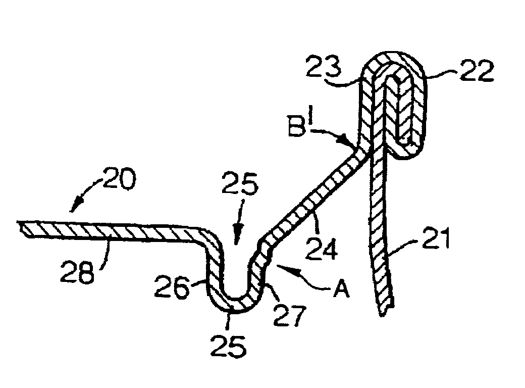
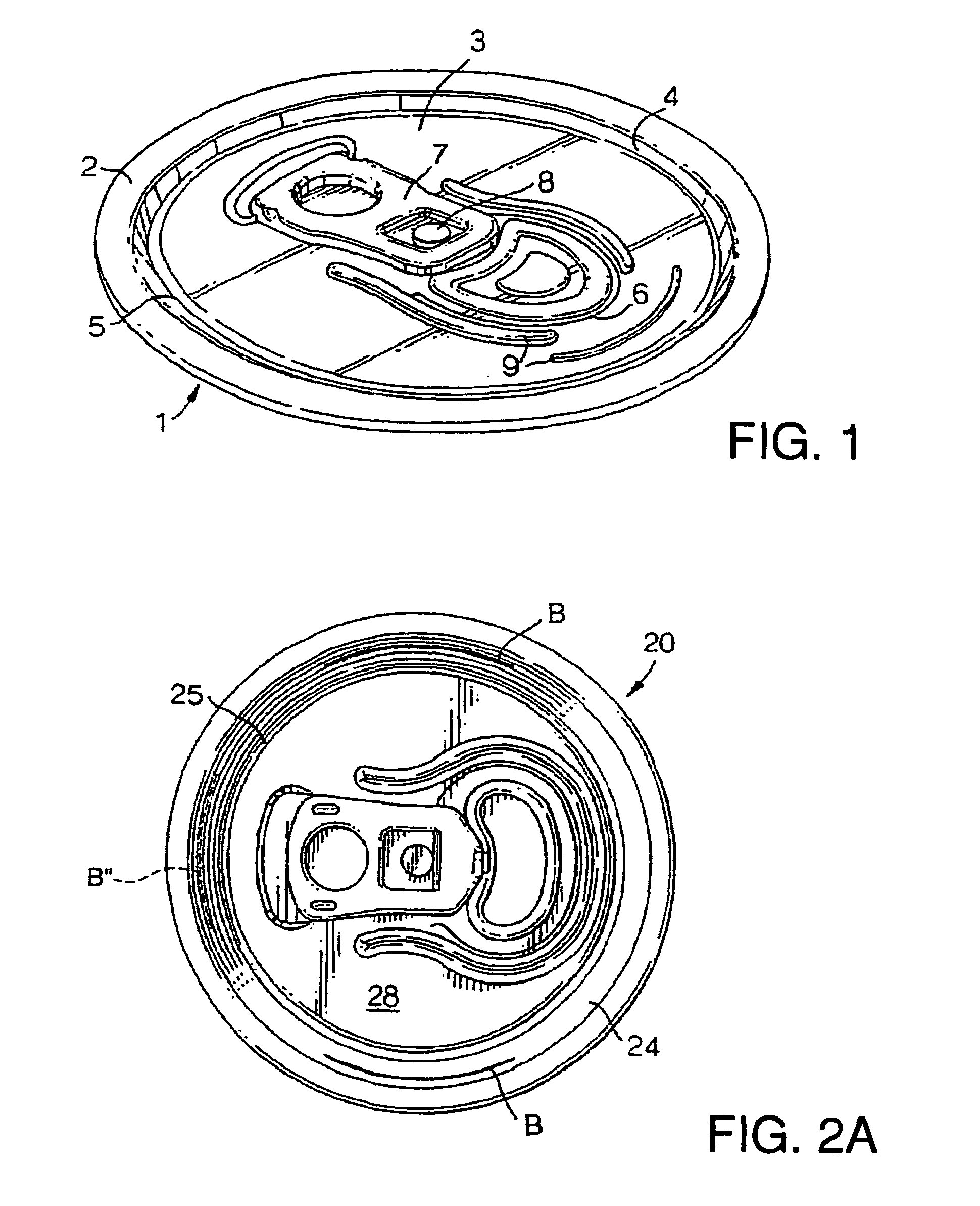
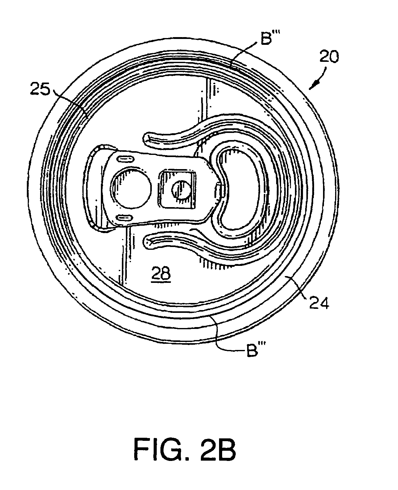
A can end having a countersink bead, an inclined chuck wall and a strong seam, resists distortion from its circular profile when subjected to thermal processing or when packaging carbonated beverages. This high hoop strength affects the manner in which the can end ultimately fails when placed under extreme abuse conditions, even if buckle pressure performance is within industry specified standards. The can end of the invention has control features introduced which control the failure mode whilst maintaining specified buckle pressure performance. In one embodiment, the control feature comprises expansion of the countersink bead to act as a trigger for local peaking, together with a groove in the chuck wall which prevents the peaking force from being concentrated at a single point which could result in leaking by the production of a pin hole.

Description

[0001]This is a continuation of application Ser. No. 10 / 770,791 filed Feb. 3, 2004, now abandoned which is a continuation of PCT / EP03 / 03716 filed Apr. 10, 2003, which claims priority to EPO Application Ser. No. 02252800.4 filed Apr. 22, 2002.BACKGROUND OF THE INVENTION[0002]This invention relates to a can end and a method of manufacture of such a can end. In particular, it relates to a can end which has improved performance characteristics.[0003]Containers such as cans which are used for the packaging beverages, for example, may contain a carbonated beverage which is at a higher than atmospheric pressure. Can end design has been developed to withstand this “positive” buckle pressure (sometimes also referred to as “peaking” pressure) up to defined minimum values (currently 90 psi for carbonated soft drinks) under normal operating conditions before failure. About 8 to 10 psi above this value, failure of conventional can ends involves loss of the circular profile and buckling of the en...

Claims


Application Information

Patent Timeline
Patent Type & Authority Patents(United States)
IPC IPC(8): B65D17/34B65D6/28B21D51/38B21DB21D51/44B65DB65D8/04B65D8/06B65D8/12B65D8/20
CPCB65D17/08Y10S220/906
Inventor WATSON, MARTIN JOHNFIELDS, BRIANLOCKLEY, ANDREW ROBERT
Owner CROWN CORK & SEAL TECH CORP
Learn More