
Door position indicating mechanism for a railcar

a technology for indicating mechanisms and railcars, which is applied in the direction of railway components, tipping wagons, wagons/vans, etc., can solve the problems of limiting the open area of the car's bottom, additional costs and potential damage to the car, and achieves the effects of convenient inspection, reliable, accurate and inexpensiv

Inactive Publication Date: 2008-05-06
VERTEX RAILCAR CORP
View PDF8 Cites 7 Cited by
  • Summary
  • Abstract
  • Description
  • Claims
  • Application Information

AI Technical Summary

Benefits of technology

"The present invention provides a door position indicating mechanism for a railcar that physically monitors the operating lever of the system, rather than the movable air cylinder shaft. This mechanism is easy to see, reliable, accurate, and inexpensive. It can be installed on new railcar construction or retrofitted onto existing railcars."

Problems solved by technology

There are several disadvantages to the hopper door operating mechanisms described in some of the aforementioned patents.
One problem is that some of the prior art mechanisms are designed such that each actuating mechanism is connected to doors from two separate hoppers.
Another disadvantage of some of the above described hopper door mechanisms is that the operating mechanisms limit the distance of the door motion, thus limiting the open area of the car's bottom.
This arrangement slows the unloading process and causes additional costs and potential damage to the car due to increased periods in thaw sheds.
However, many of these systems usually require automatic operation of the doors, which requires an operating cylinder and valving.
Many automatic door systems are designed with an overcenter latch to insure that the doors will not inadvertently open, as this could cause serious injury and / or damage to occur.
One problem which may occur with an operating cylinder is a condition in which the air cylinder is leaking, allowing the movable shaft within the cylinder to falsely indicate the actual state of the cylinder (activated or deactivated).
Another potential disadvantage of using an air cylinder operating door system is that the air cylinder is usually physically located where it is difficult to actually observe the movement of the movable shaft actuating the hopper doors.

Method used


Image

  • Door position indicating mechanism for a railcar
  • Door position indicating mechanism for a railcar
  • Door position indicating mechanism for a railcar

Examples


Embodiment Construction

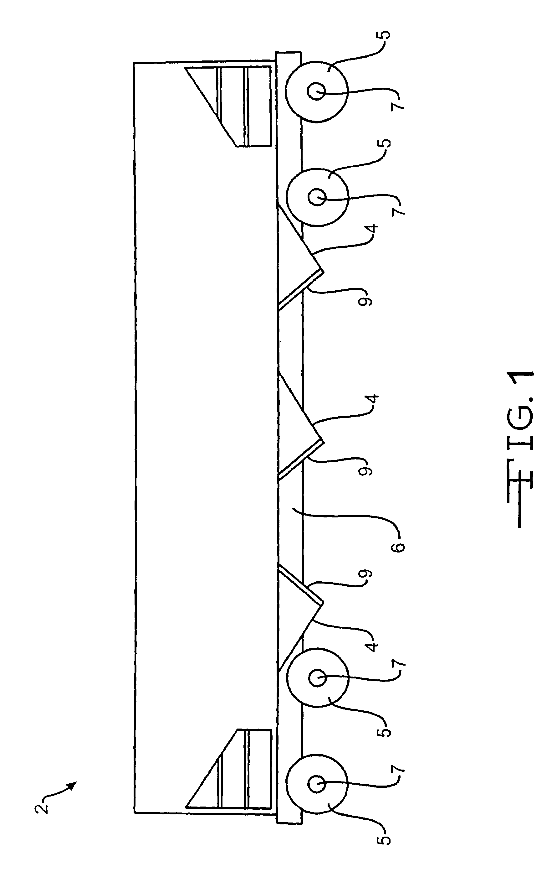
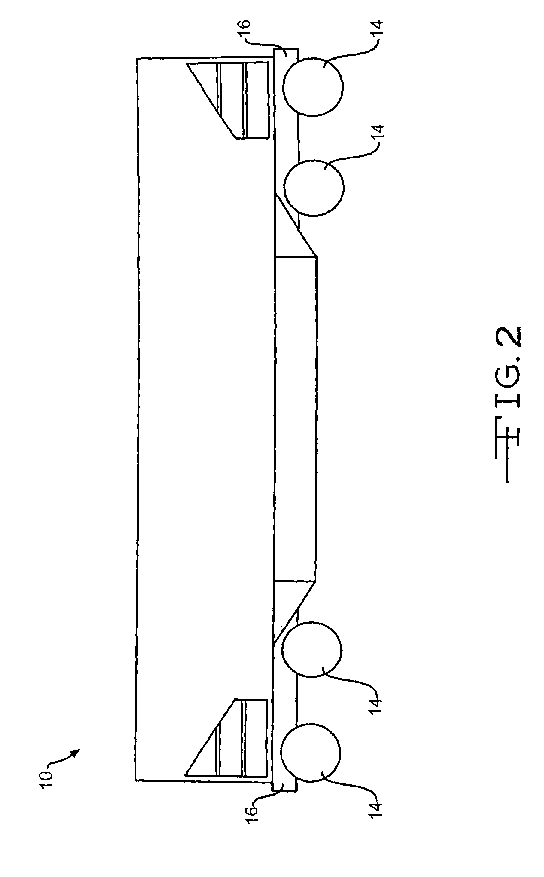
[0025]FIGS. 1-3 display three different major types of hopper cars. FIGS. 1 and 3 show hopper cars using transverse doors, while FIG. 2 shows a car using longitudinal doors.

[0026]Referring now to FIG. 1, there is shown a typical three pocket railway hopper car, generally designated at 2, which may be equipped with a preferred embodiment of the present invention. Car 2 is provided with a plurality of hopper units 4, a plurality of wheels 5, and a longitudinally extending center sill 6. Wheels 5 are mounted on a series of truck axles 7. Each hopper unit 4 is provided with a door 9 which is moveable to open and close each hopper unit 4. An actuating system for this type of car is taught in U.S. patent application Ser. No. 10 / 863,887, filed Jun. 8, 2004, which application is incorporated herein by reference.

[0027]Referring now to FIG. 2, there is shown a typical hopper railcar, generally indicated at 10, having longitudinal doors which may be equipped with a preferred embodiment of the ...


PUM


Abstract

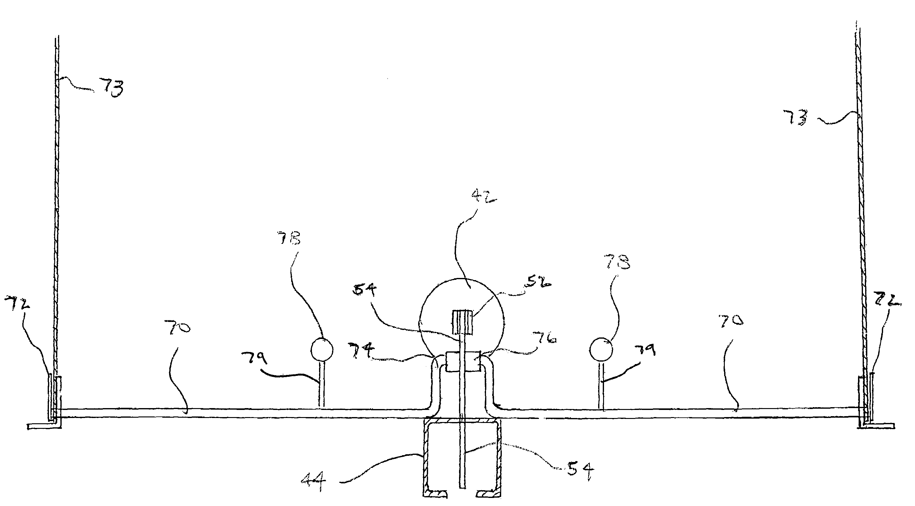
A door position indicating mechanism for use with a railroad car. The mechanism includes a shaft which extends across the longitudinal direction of the car. An offset section of the shaft has a roller which contacts a lever which is shifted by an air cylinder when operating the door mechanism. At least one counterweight biases the roller into constant contact with the door operating lever. Indicators are mounted on either end of the shaft such that the position of the doors can be noted from either side of the railroad car.

Description

CROSS-REFERENCE TO RELATED APPLICATIONS[0001]This application claims benefit from U.S. Provisional Patent Application Ser. No. 60 / 605,814 filed Aug. 31, 2004, which application is incorporated herein by reference.BACKGROUND OF THE INVENTION[0002]1. Field of the Invention[0003]This invention relates generally to railcars and, in particular, to an indicating mechanism for monitoring the hopper doors of a railcar.[0004]2. Description of the Related Art[0005]A common type of railroad freight car in use today is the freight car of the type wherein the load is discharged through hoppers in the underside of the body. Such cars are generally referred to as hopper cars and are used to haul coal, phosphate and other commodities.[0006]After hopper cars are spotted over an unloading pit, the doors of the hoppers are opened, allowing the material within the hopper to be emptied into the pit.[0007]Hopper cars, which may be covered, are usually found with one of two hopper configurations: transver...

Claims


Application Information

Patent Timeline
Patent Type & Authority Patents(United States)
IPC IPC(8): B61D3/00
CPCB61D7/24
Inventor TAYLOR, FRED J.
Owner VERTEX RAILCAR CORP
Learn More