String type air damper

a technology of air damper and string, which is applied in the direction of shock absorbers, wing accessories, manufacturing tools, etc., can solve the problems of complicated hooking work, and achieve the effects of reducing the number of screws, and ensuring the quality of the string

Inactive Publication Date: 2008-05-06
PIOLAX CO LTD
View PDF22 Cites 9 Cited by
  • Summary
  • Abstract
  • Description
  • Claims
  • Application Information

AI Technical Summary

Benefits of technology

[0015]As described above, in the first aspect, the string member and the piston are formed integrally. Therefore, unlike the string type air damper according to the related art, it is unnecessary to form a loop at the base end of the string member being accompanied by a complicated work, and also it is unnecessary to form a hook portion in the piston and to hook the loop-shaped base end of the string member at the hook portion of the piston. Accordingly, the string type air damper can be very easily assembled.
[0016]In the second aspect, the string member branching into a plurality of portions supports the piston. Therefore, it can be guaranteed that the piston is stably moved in the cylinder. In the third aspect, the string member is formed into a belt shape. Therefore, it is possible to strengthen the string member itself. At the same time, the string member can be smoothly bent and guided along an arcuate face of the guide hole. In the fourth aspect, a reinforcing plate formed of the second material harder than the first material is provided on an upper face of the piston formed of the first material. Therefore, an end portion of the helical spring can be positively supported.
[0017]In the fifth aspect, the string member and the guide cap are integrally formed and the forward end portion of the string member is hooked at the piston and then introduced outside. Therefore, unlike the string type air damper according to the related art in which a loop is formed at the base end portion of the string member and the thus formed loop-shaped base end portion of the string member is hooked at the hook portion arranged in the guide cap being accompanied by a complicated work, it is unnecessary to do the above complicated work according to the present invention. Accordingly, the string type damper can be easily assembled.

Problems solved by technology

However, in the string type air damper according to the related art, the following problems may be encountered.
Therefore, this hooking work is complicated.

Method used


Image

  • String type air damper
  • String type air damper
  • String type air damper

Examples


first embodiment

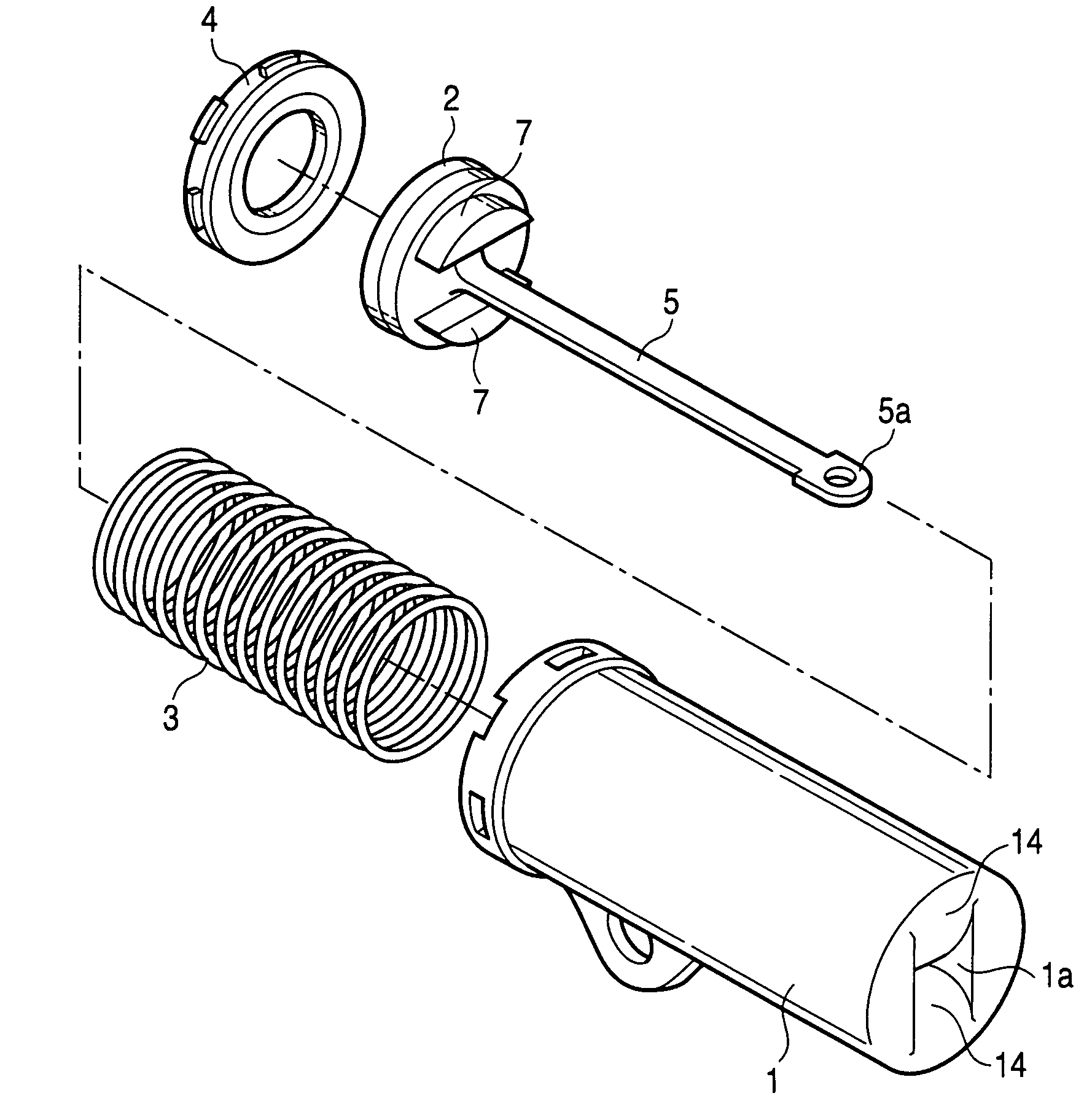
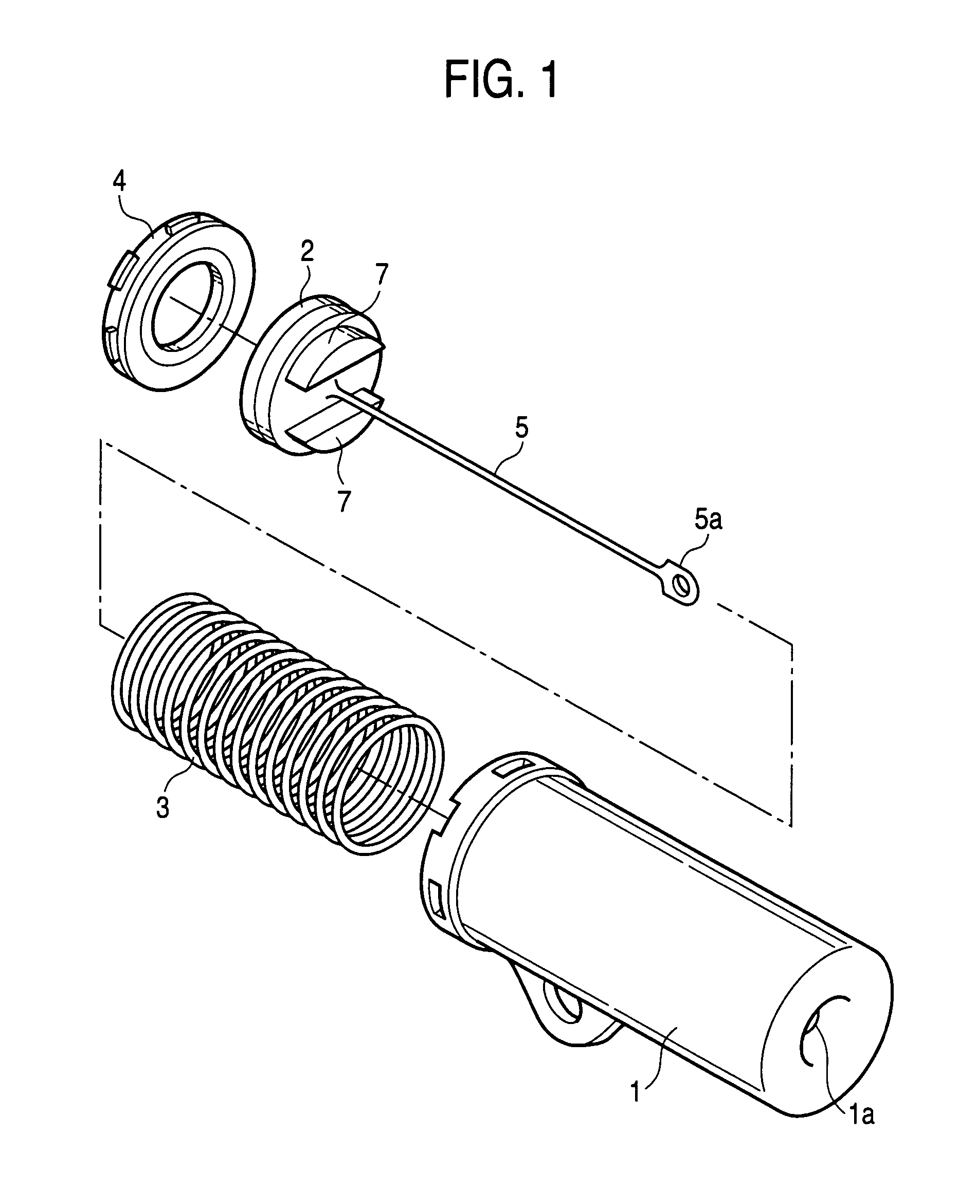
[0032]Referring to the drawings, preferred embodiments of the invention will be explained in detail as follows. As shown in FIG. 1, a string type air damper includes a cylinder 1, a piston 2, a helical compression spring 3, an end cap 4, and a string member 5. The cylinder 1 defines a guide hole 1a at one end portion thereof. The piston 2 moves in the cylinder 1. The helical compression spring 3 biases the piston 2 toward the other end portion of the cylinder 1. The end cap 4 is attached to the other end side of the cylinder 1. The string member 5 is connected with the piston 2 and guided outside through the guide hole 1a. In this connection, reference numeral 7 denotes a mount for receiving the end portion of the helical compression spring 3 provided in the piston 2.

[0033]In the first embodiment, as shown in FIG. 2A, the piston 2 and the string member 5 having a large diameter and a short length are integrally formed by means of an injection molding using a metallic mold 8 for mol...

second embodiment

[0037]In the second embodiment, in the case where the piston 2 and the string member 5 are integrally molded, as shown in FIG. 6A, the piston 2 and the string member 5 having the large diameter and the short length are integrally formed by means of injection molding using the metallic mold 8 for molding the piston and the metallic mold 9 for molding the forward end portion of the-string member 5. After the completion of injection molding, as shown in FIG. 6B, when the metallic mold 9 for molding the forward end portion of the string member 5 is linearly moved away from the metallic mold 8 for molding the piston, the string member 5 having the large diameter and the short length is elongated to make the string member have the small diameter and the long length.

[0038]In the second embodiment, the string member 5 branches into the two portions. However, it should be noted that the present invention is not limited to the above specific embodiment. For example, as shown in FIG. 7, it is ...

fifth embodiment

[0043]In this case, although a specific structure is not shown in the drawing, the guide cap 6 and the string member 5 having the large diameter and the short length are integrally molded by means of injection molding using the metallic mold for forming the guide cap and the metallic mold 9 for molding the forward end portion of the string member 5. After the completion of injection molding, when the metallic mold 9 for molding the forward end portion of the string member 5 is linearly moved away from the metallic mold for molding the guide cap, the string member 5 having the large diameter and the short length is elongated to make the string member have the small diameter and the long length. In the fifth embodiment, the string member branches into two portions on the base end portion side and integrally connected with the guide hole 6a edge of the guide cap 6.

[0044]Therefore, the string type air damper according to the fifth embodiment is assembled as follows. As shown in FIG. 13,...


PUM


Abstract

A string type air damper includes a cylinder formed in a tubular shape, defining a guide hole at one end portion thereof, a piston, which moves in the cylinder, a helical spring for biasing the piston toward the other end portion of the cylinder, and a string member guided from inside of the cylinder to outside thereof through the guide hole. The piston and the string member are integrally formed. Since the string member is formed integrally with the piston, unlike a method according to a related art, it becomes unnecessary to form a loop at the base end portion of the string member with a complicated work and form a hook portion at the piston and hook the base end portion of the string member at the hook portion of the piston. Therefore, the string type air damper can be very easily assembled.

Description

[0001]The present disclosure relates to the subject matter contained in Japanese Patent Application No. 2002-275134 filed on Sep. 20, 2002, which is incorporated herein by reference in its entirety.BACKGROUND OF THE INVENTION[0002]1. Field of the Invention[0003]The present invention relates to improvements in a string type air damper, for example, used for a glove box of an automobile.[0004]2. Description of the Related Art[0005]Although a specific example of this type air damper according to a related art is not shown in the drawing, it includes: a cylinder, both end portions of which are open; a piston moving in the cylinder; a string member, the base end of which is connected with the piston; a valve device for controlling a volume of air passing through the valve, attached to the other end side of the cylinder; a guide cap for guiding the string member, attached on one end side of the cylinder; and a helical compression spring for pushing the piston to the other end of the cylin...

Claims


Application Information

Patent Timeline
Patent Type & Authority Patents(United States)
IPC IPC(8): E05F5/08F16F9/00E05F3/02E05F3/10F16F9/02F16F9/32
CPCE05F3/02E05F3/108F16F9/0218F16F9/0227F16J7/00F16J1/12E05Y2900/538Y10T16/62Y10T16/281Y10T16/282Y10T16/625F16F9/02
Inventor ITO, KIICHIRO
Owner PIOLAX CO LTD
Why Eureka
Try Eureka