Hermetically sealed housing with interior capture plate

Inactive Publication Date: 2008-04-08
MAXTOR
View PDF61 Cites 26 Cited by
  • Summary
  • Abstract
  • Description
  • Claims
  • Application Information

AI Technical Summary

Benefits of technology

[0011]The present invention is generally directed to a system for eliminating openings in the cover and / or base plate of a hard disk drive assembly to thereby reduce the available pathways for leakage of low density gas within the disk drive assembly. In one embodiment, the spindle motor shaft is secured between an independent capture plate and the base plate. The capture plate is separate from the cover and is secured to the base plate at a position inside the cover perimeter. The presence of the capture plate eliminates the need for forming openings in the cover for purposes of securing the spindle shaft. In a second embodiment, the capture plate may extend to and engage the actuator shaft, thereby eliminating a second opening in the cover. Each embodiment provides improved structural rigidity, assists with proper alignment of the spindle shaft and actuator shaft alone and / or relative to each other, and reduces head migration (TMR) and disruptions due to mechanical shocks. The capture plate further allows alignment of the spindle shaft and actuator shaft independent of the cover. In addition, the capture plate may be configured to enclose a substantial portion or all of the upper area of the disk stack and thereby lower air turbulence and enhance disk drive performance. Air turbulence can be further reduced and performance improved by shrouding the perimeter edge of the disk stack. In one embodiment, this can be accomplished by configuring the interior of the base plate to approximate the perimeter shape of the disk stack forming a wall closely adjacent the edge of the disk or disks forming the disk stack.
[0012]In other embodiments, the capture plate may take on various alternative configurations. To provide enhanced stiffness and enhanced damping, the capture plate may have planar portions formed at different planes relative to each other. In addition, a layer of damping material may be adhered to one or more surfaces of the capture plate to provide further damping characteristics. The capture plate also may be constructed as a laminate made from two or more layers of metal or other materials such as acrylic-based pressure-sensitive adhesives.

Problems solved by technology

However, decreasing the width of tracks makes it more difficult for the read / write heads to accurately read and write information to and from the narrowing tracks.
Not only is it difficult to physically position the read / write element over a narrow width track, but it is increasingly difficult to maintain the read / write element over the track at an optimal position for accurate data transfer.
Air turbulence created by the spinning disks, disk flutter and spindle vibrations, temperature and altitude can all adversely effect registration of the read / write element relative to the tracks.
Moreover, increasing the speed of the rotating disks to achieve increased data access times increases air turbulence, which increases misregistration between the read / write element and the tracks on the storage disks (track misregistration or TMR).
Accuracy can be further adversely effected if the read / write heads are not maintained within an optimum height range above the surface of the storage disk.
However, since the disk rotates many thousands of revolutions per minute or more, continuous direct contact between the slider and the recording medium can cause unacceptable wear on these components.
Excessive wear on the recording medium can result in the loss of data, among other things.
Excessive wear on the slider can result in contact between the read / write transducer and the disk surface resulting, in turn, in failure of the transducer, which can cause catastrophic failure.
In non-contact disk drives there are also limitations on how close a read / write element may be to the surface of a disk.
These factors, as well as air turbulence, disk flutter and spindle vibration, can cause the read / write element flying height to vary or even cause the read / write element to contact the spinning disk.
Such seals are not designed to prevent internal air and other gases from exiting through the seal and out of the drive.
Some low density gases also have greater thermal conductivity, which results in better motor efficiencies and therefore lower power consumption for a given performance level.
Despite these advantages, low density gas-filled drives have not been commercially successful.
It has been difficult to prevent the low density gas from escaping from the sealed drive environment.
Conventional rubber or paper seals or gaskets used in air-filled drives are inadequate at preventing leakage of low density gas due to the smaller atom size of low density gases, such as helium, compared to air.
Thus, over time, the necessary threshold quantity of low density gas may be lost within the drive-environment and may or may not be replaced with ambient air.
As the low density gas leaks out of a drive and is replaced by air, the drive is subject to undesirable operational effects possibly leading to unacceptable error rates and / or failure of the drive.
For example, the increased concentration of air may increase the turbulent forces on the heads due to the increased drag forces within the drive which may further cause the heads to fly at too great a distance above the disks and potentially increasing instances of read / write errors.
If the low density gas leaks from the sealed environment over time and is not replaced by ambient air, problems will occur such as the heads flying at a distance too close or in contact with the disks, thereby increasing instances of read / write errors as well as damage to the disk surface and head and higher operating temperatures due to a reduction in conduction cooling.
Each creates a reliability risk.
The risk of unanticipated failures due to inadequate amounts of low density gas within the drive is a draw back to low density gas-filled drives.
Indeed, data stored within the drive may be irretrievably lost if the drive fails due to the loss of the low density gas environment.

Method used


Image

  • Hermetically sealed housing with interior capture plate
  • Hermetically sealed housing with interior capture plate
  • Hermetically sealed housing with interior capture plate

Examples


Embodiment Construction

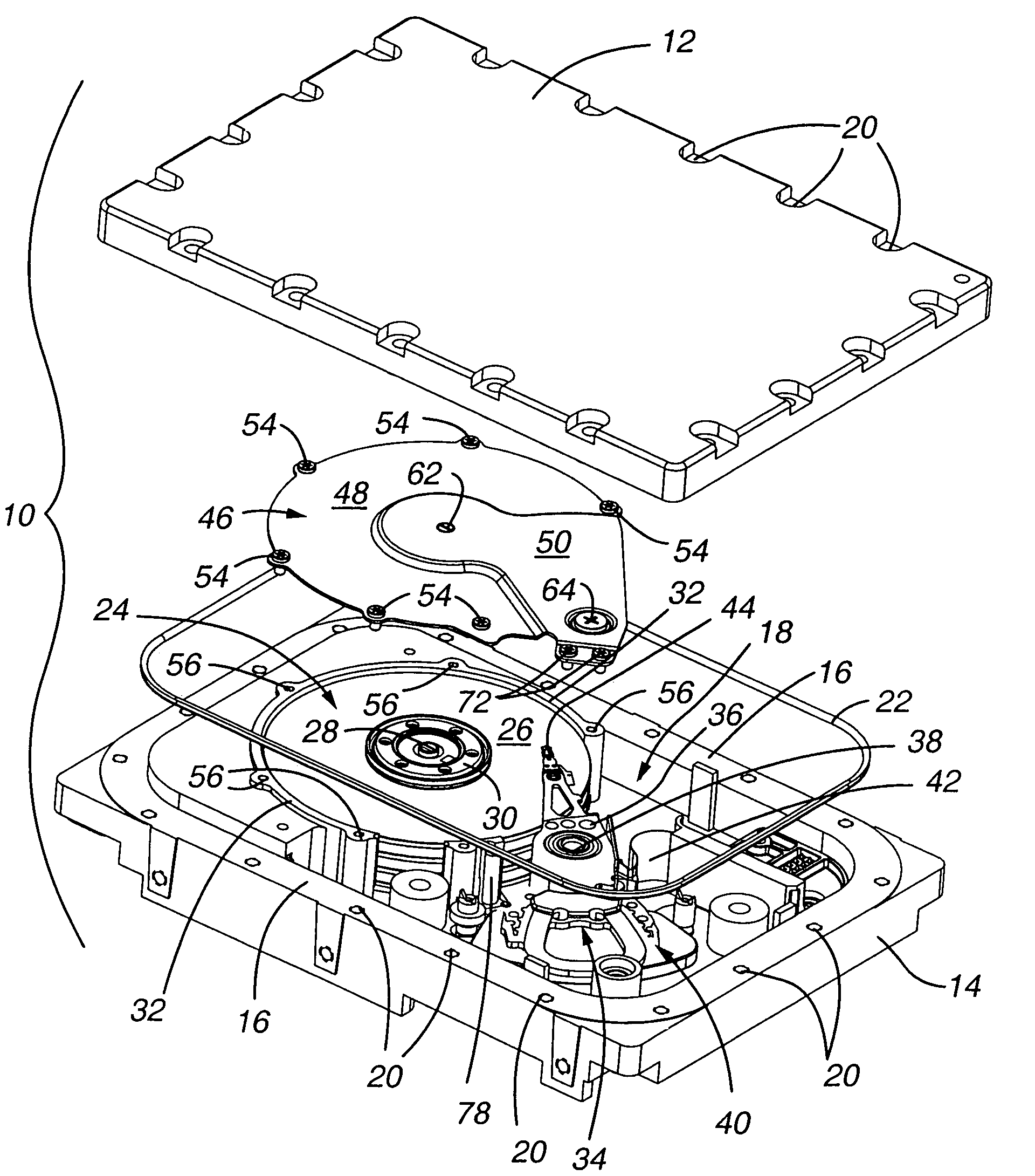
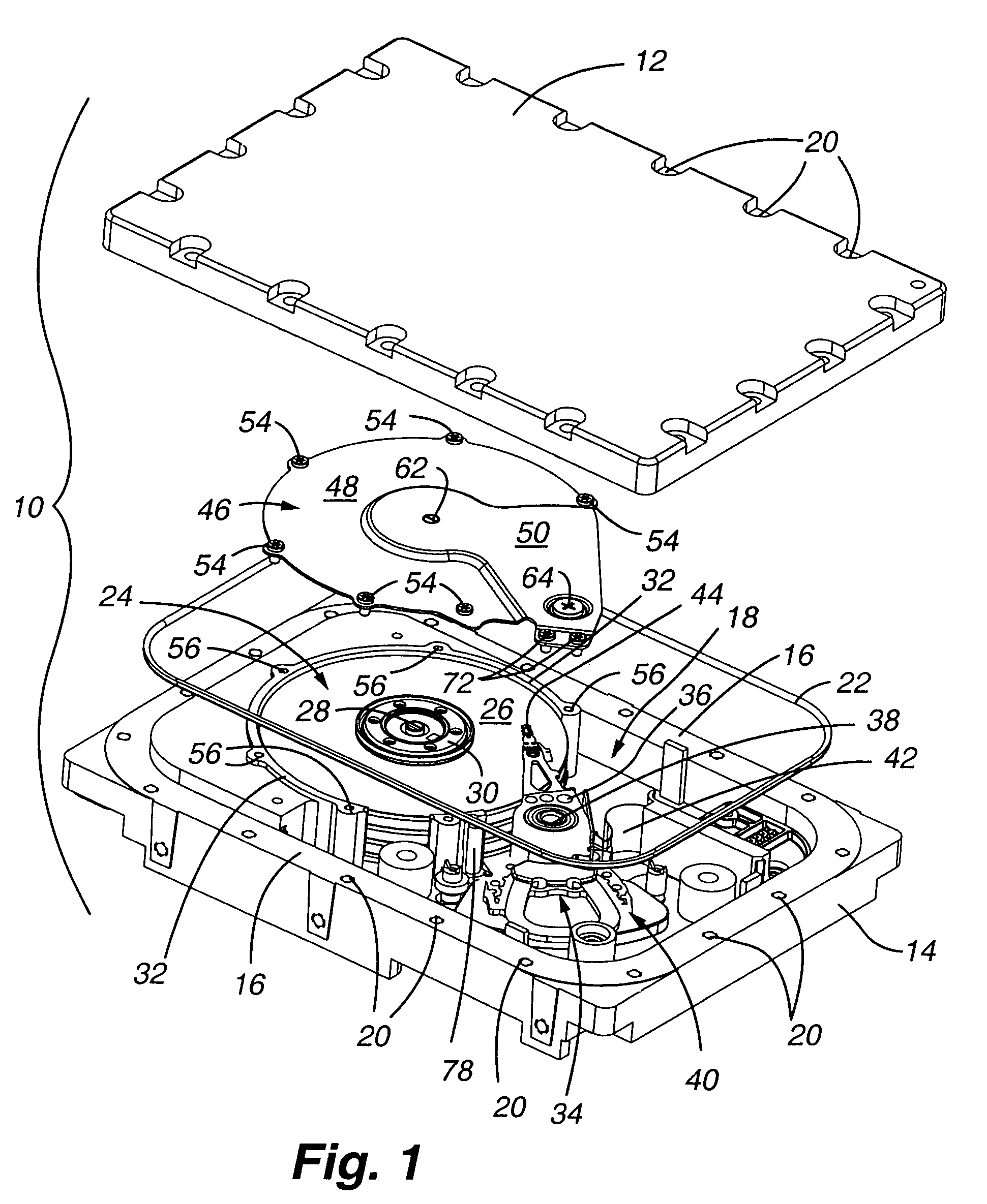
[0030]Turning to FIG. 1, an exploded perspective view of a disk drive of the present invention is shown. The disk drive assembly 10 generally comprises a cover 12 and base plate 14. The base plate has perimeter walls 16 which define an inner chamber 18. When the cover plate is secured to the base plate, the inner chamber is filled with a low density gas such as helium to create a pressurized low density gas environment for operation of the disk drive components. The cover plate and base plate are provided with aligned apertures 20 equally spaced around the perimeter of each for securing the cover to the base plate. The apertures within the base plate are typically threaded to receive fasteners (not shown). Additionally, it has been determined that a metal C-shaped seal 22 is more suitably adapted to maintaining the pressurized low density gas environment within the chamber 18 than a conventional rubber seal. In the preferred embodiment, the cover and base plate are secured by the fa...


PUM


Abstract

A method and apparatus for aligning and securing a spindle shaft and actuator shaft in a low-density gas-filled hard disk drive and independent of the disk drive cover is provided. A capture plate is positioned above the memory disk(s) and is secured to the base plate. The spindle shaft and, optionally, the actuator shaft are secured between the base plate and capture plate. The capture plate may be configured to reduce vibration. This structure eliminates use of the cover to secure the spindle shaft and actuator shaft and, thereby, eliminates a potential pathway for low-density gas to escape. The capture plate may also be configured to reduce air turbulence created by the rotating disk and reduce track misregistration of the read / write element(s).

Description

FIELD OF THE INVENTION[0001]The present invention relates to hard disk drives filled with low-density gas. More particularly, the present invention relates to a system of aligning and securing the spindle motor shaft and actuator shaft without using the cover of the disk drive assembly and other techniques to maintain an appropriate volume of low-density gas within the disk drive assembly over an acceptable time period.BACKGROUND OF THE INVENTION[0002]Hard disk drives incorporate magnetic storage disks and read / write heads which are capable of reading data from and writing data onto the rotating storage disks. Data is typically stored on each magnetic storage disk in a number of concentric tracks on the disk. The read / write heads, also referred to as read / write transducers or read / write elements, are integrated within a slider. The slider, in turn, is part of an actuator assembly which positions the heads relative to the surface of the storage disks. This may be at a predetermined h...

Claims


Application Information

Patent Timeline
IPC IPC(8): G11B33/14G11B23/03
CPCG11B25/043G11B33/1486
Inventor GIFFORD, BRUCEANDRIKOWICH, THOMAS G.STRZEPA, MICHAEL C.O'DAY, RICHARD
Owner MAXTOR
Why Eureka
Try Eureka