
Method and means for shifting a hydromechanical transmission

a technology of hydromechanical transmission and shifting mode, which is applied in the direction of gearing control, gearing element, gearing, etc., can solve the problems of limited maximum torque capacity of synchronizer, inactive control of the speed of this unit, and still remain problems, so as to achieve high-quality shifting

Inactive Publication Date: 2008-04-08
SAUER DANFOSS NORDBERG
View PDF9 Cites 37 Cited by
  • Summary
  • Abstract
  • Description
  • Claims
  • Application Information

AI Technical Summary

Benefits of technology

This method improves shifting quality by actively controlling hydrostatic units during shifts, allowing for smooth transitions between modes without changing transmission ratios, even in the torque dead zone, thereby enhancing torque and speed conditions.

Problems solved by technology

Unfortunately, synchronizers have limited maximum torque capacity and also require torque to drop below a threshold to complete the shift.
Consequently, when a shift is made with one of the hydrostatic units at or near zero displacement, there is not active control of this unit's speed.
Though advances have been made in the hydromechanical transmission art, problems still remain.
Consequently, both low displacement and speed can cause tolerance and gain issues that interfere with achieving the desired speed and torque conditions necessary for a proper shift.

Method used


Image

  • Method and means for shifting a hydromechanical transmission
  • Method and means for shifting a hydromechanical transmission
  • Method and means for shifting a hydromechanical transmission

Examples


Embodiment Construction

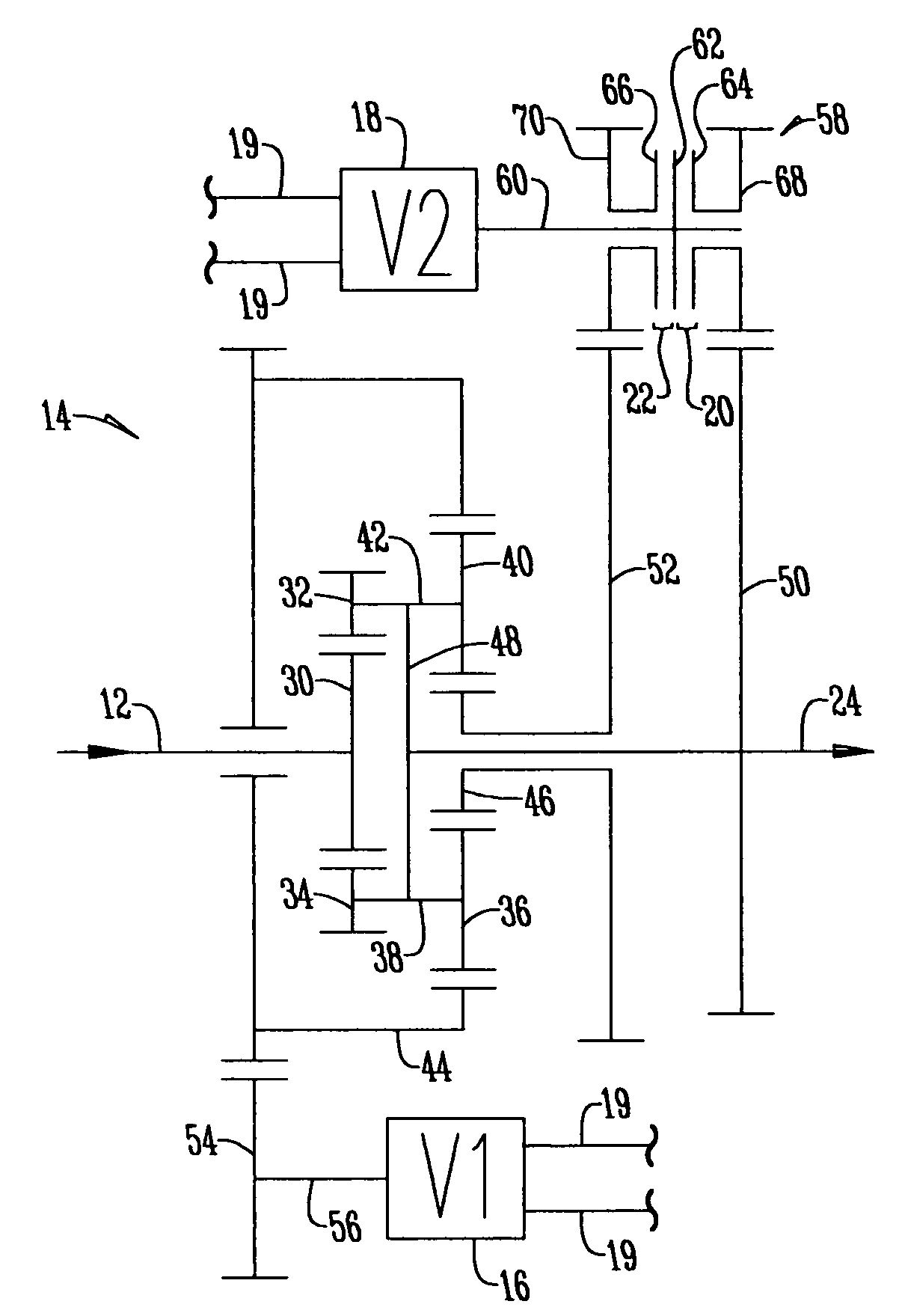
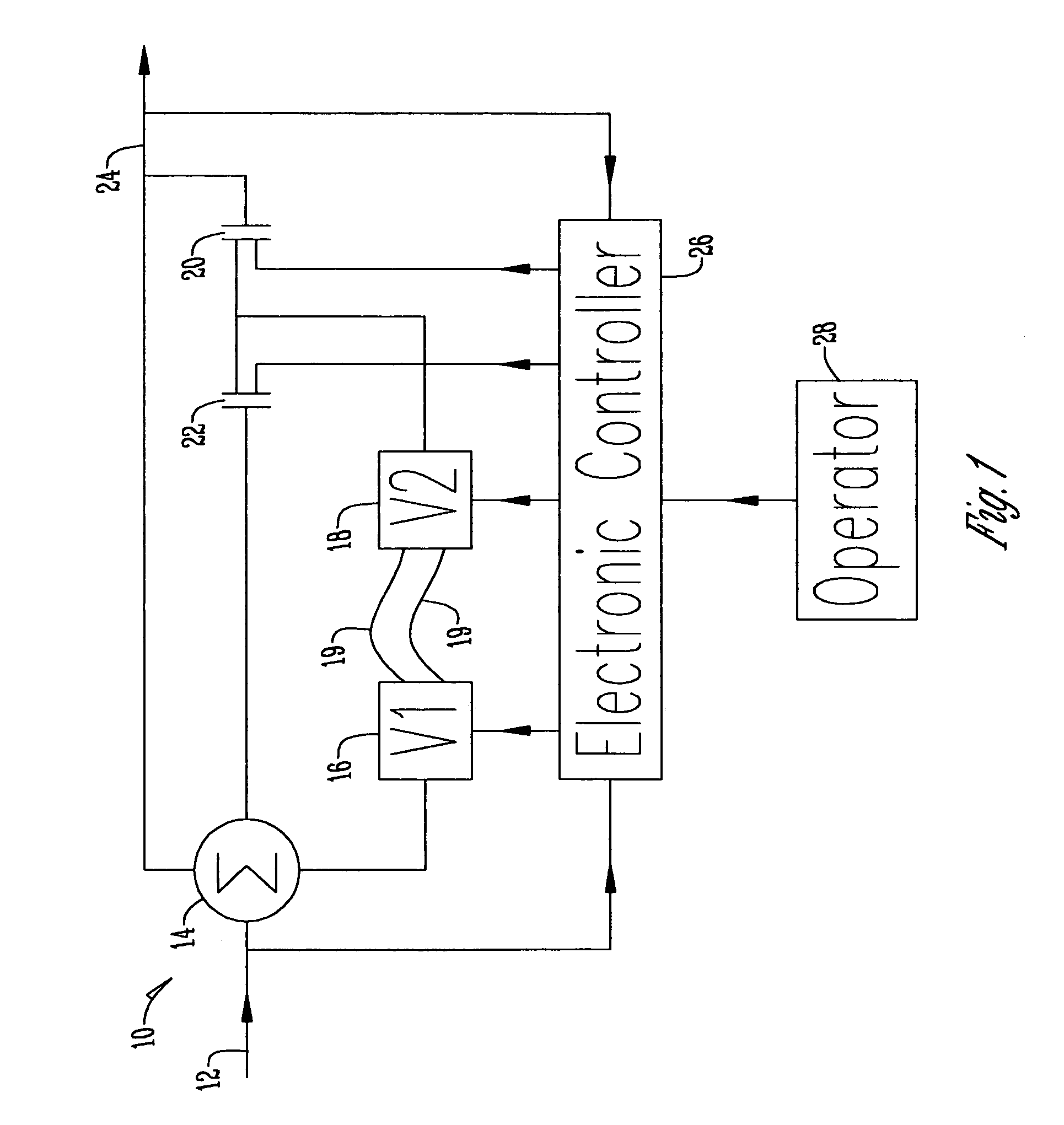
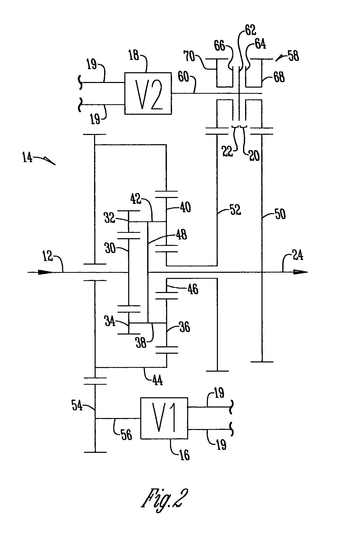
[0028]FIG. 1 shows a block diagram of the two-mode hydromechanical transmission 10 of the present invention. The transmission 10 has an input shaft 12 that is rotatably connected to a planetary gear system 14. Rotatably connected to the planetary gear system 14 is a first variable displacement hydrostatic unit 16 that is fluidly connected to a second variable displacement hydrostatic unit 18 via hydraulic fluid lines 19. The system 10 is designed such that the planetary gear system 14 can be connected to the second variable displacement hydrostatic unit 18 by a first clutch 20 or a second clutch 22, depending on the desired mode of the transmission. Depending on the rotation of the input shaft 12, the outputs of the first and second variable displacement hydrostatic units 16, 18, and the clutching of the planetary gear system 14 by clutches 20, 22, an output shaft 24 will be driven at an output rotational speed. An electronic controller or control unit 26 will monitor the rotation o...


PUM


Abstract

A method for achieving high quality shifts with one hydraulic unit near zero displacement when using dog clutches. This method includes selecting the proper displacement and vocation (whether the hydrostatic unit works as a pump or motor) of a low displacement hydraulic unit during the shift, selecting the appropriate speed differential between the clutch elements, selecting the proper vehicle speed at which to make the shift, and sequencing the displacement changes of the hydraulic units with a controller in order to achieve the desired shift conditions.

Description

BACKGROUND OF THE INVENTION[0001]This invention relates to hydromechanical transmissions. More specifically, this invention relates to a method of shifting modes within a hydromechanical transmission.[0002]Hydromechanical transmissions are frequently used in vehicles where shift quality is important and more specifically shift smoothness and continuous power delivery is important within the transmission. Within the hydromechanical transmission are a series of gears that make up separate modes within the transmission, usually a first mode for low speed and a second mode for high speed. These mode changes are usually made with a clutching element and are preferably made without a change in the transmission ratio by engaging the incoming clutch when the first and second modes are at near synchronous speeds.[0003]For efficient space utilization, dog clutches have been used to accomplish this shift. A dog clutch may be used if the clutch element speed differential is low enough and the c...

Claims


Application Information

Patent Timeline
Patent Type & Authority Patents(United States)
IPC IPC(8): F16H47/04
CPCF16H47/04F16H61/462Y10T477/638F16H61/0403
Inventor POLLMAN, FREDERIC W
Owner SAUER DANFOSS NORDBERG
Learn More