
Variable capacity climate control system for multi-zone space

multi-zone technology, applied in the field of system and method for controlling a climate control system for a space, can solve the problem of not providing an appropriate minimum level of system operation, and achieve the effect of limiting the scope of invention and preventing unnecessary operation

Active Publication Date: 2008-04-08
COPELAND COMFORT CONTROL LP
View PDF4 Cites 124 Cited by
  • Summary
  • Abstract
  • Description
  • Claims
  • Application Information

AI Technical Summary

Benefits of technology

"The present invention relates to a climate control system for a plurality of zones that can provide conditioned air to each zone. The system includes a thermostat that controls the supply of conditioned air to each zone by controlling the operation of zone dampers. The thermostat can initiate operation of the circulating air blower and cooling system at less than full capacity when there is a significant change in sensed temperature in a zone, and will switch to full capacity operation when a predetermined number of zones transmit a significant change in sensed temperature. The system also includes a display that shows the system error if there is no significant change in sensed temperature for a predetermined time period. This allows for correction of any problems with the system. Overall, the invention provides efficient and effective climate control for multiple zones."

Problems solved by technology

However, such systems have often employed a bypass damper to address the problem of high circulating air pressure that results when most of the dampers are closed and only a few zones are being supplied with conditioned air.
Such systems do not provide an appropriate minimum level of system operation to supply conditioned air to only a few zones that require heating or cooling.

Method used


Image

  • Variable capacity climate control system for multi-zone space
  • Variable capacity climate control system for multi-zone space

Examples


Embodiment Construction

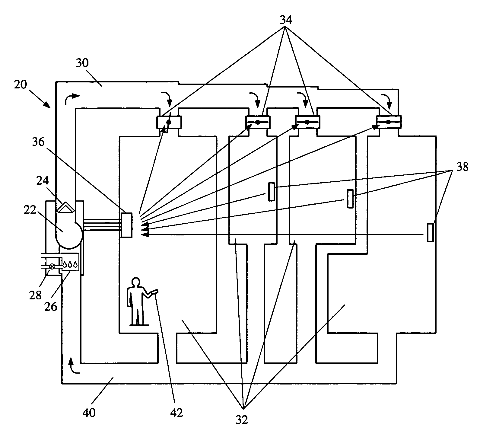
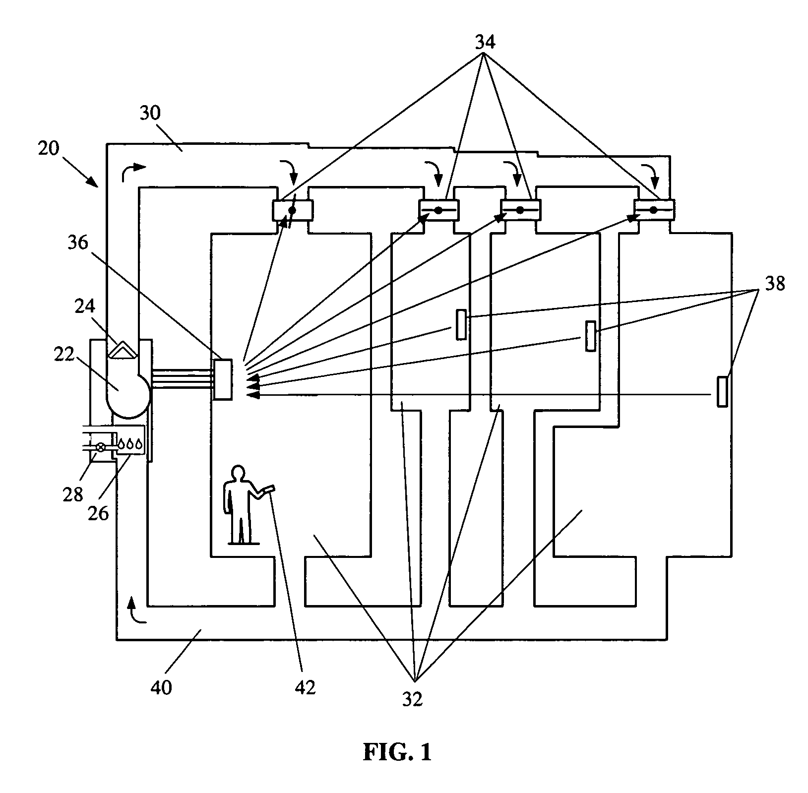
[0009]One embodiment of a multi-stage climate control system for a multi-zone space according to the principles of the present invention is shown generally at 20 in FIG. 1. The climate control system 20 comprises a variable speed circulating air blower 22 and a multi-stage cooling system 24 having at least a full capacity mode and a less than full capacity mode of operation for providing conditioned air to a space. The climate control system 20 may further comprise a multi-stage heating system 26 having at least a full capacity mode and a less than full capacity mode of heating operation for providing conditioned air to a space. Such a heating system, for example, may comprise a multi-stage gas valve for providing at least two levels of gas flow. The flow of conditioned air is supplied to the space through a supply duct 30 to a plurality of zones 32 within the space, where a plurality of controllable zone dampers 34 control the supply of conditioned air into the plurality of zones 3...


PUM

PropertyMeasurementUnit
temperatureaaaaaaaaaa
offset temperatureaaaaaaaaaa
temperatureaaaaaaaaaa

Abstract

A climate control system having two or more stages of cooling operation or heating operation is provided for supplying conditioned air to a plurality of zones within a space, where the climate control system comprises a plurality of controllable zone dampers for controlling the supply of conditioned air to each of the plurality of zones, and a plurality of zone temperature sensors for periodically sensing temperature at preset intervals and transmitting sensed temperature information when the temperature of the zone has changed by more than a predetermined amount. The climate control system further comprises a thermostat that is adapted to initiate operation of the circulating air blower and the cooling system at less than full capacity when at least one zone temperature sensor transmits a sensed temperature that differs from the set point temperature by more than a specific amount, wherein the thermostat switches the circulating air blower and cooling system to full capacity operation when either the cooling system has operated at less than full capacity for more than a predetermined time or when more than a predetermined number of zone temperature sensors transmit sensed temperatures that differ from the set point temperature by more than a specific amount.

Description

FIELD OF THE INVENTION[0001]This invention relates generally to a system and method for controlling a climate control system for a space having a plurality of zones, and more particularly to a variable capacity climate control system having a thermostat for controlling the supply of conditioned air to a plurality of zones.BACKGROUND OF THE INVENTION[0002]Multi-zone heating and cooling systems are often utilized for supplying conditioned air to the particular zones within a space requiring heating or cooling. These systems are often used to supply conditioned air to a plurality of zones within the space, and include controllable zone dampers for permitting the flow of conditioned air to each zone. However, such systems have often employed a bypass damper to address the problem of high circulating air pressure that results when most of the dampers are closed and only a few zones are being supplied with conditioned air. When only one or two zones require heating, for example, the heati...

Claims


Application Information

Patent Timeline
Patent Type & Authority Patents(United States)
IPC IPC(8): F24F7/00F25D17/04G01K13/00G01M1/38G08B17/00
CPCF24F3/0442F24F11/001F24F11/0012Y02B30/767F24F2011/0068Y02B30/746F24F11/0079F24F11/30F24F2110/00F24F2110/10F24F11/56F24F11/77F24F11/74Y02B30/70F24F11/38
Inventor CAREY, STEVEN L.EDGAR, JEFFFREDRICKS, THOMAS J.
Owner COPELAND COMFORT CONTROL LP
Learn More