Space telecommunications integrated antenna system for mobile terrestrial stations (Satcoms)

a technology of integrated antennas and space telecommunications, applied in the direction of antennas, antenna details, antenna adaptation in movable bodies, etc., can solve the problems of inconvenient way, cost, performance, and come up with difficulties relative to electronically scanned antennas, and achieve compact and integrated

Inactive Publication Date: 2008-04-01
THALES SA
View PDF6 Cites 12 Cited by
  • Summary
  • Abstract
  • Description
  • Claims
  • Application Information

AI Technical Summary

Benefits of technology

[0015]The antenna system according to the invention has the decisive advantage of using a simple fixed-beam, passive, flat antenna whose design can be optimized for the inclination of the beam chosen. The radio-electrical performance in terms of antenna gain in the axis of the beam, as well as of off-axis radiation in terms of minor lobes are then optimal and kept constant whatever the aiming sought.
[0016]The antenna system of the invention also has the advantage of being compact and integrated. The rotation on both axes enables a significant field of aim to be covered. The volume initially necessary for the displacement of the parabola is freed to make way for equipment associated with the antenna.

Problems solved by technology

A part of these devices is sometimes transferred into other compartments of the station, often in an inconvenient way.
This approach nevertheless comes up against difficulties relative to the electronically scanned antenna, namely cost, performance, etc.

Method used


Image

  • Space telecommunications integrated antenna system for mobile terrestrial stations (Satcoms)
  • Space telecommunications integrated antenna system for mobile terrestrial stations (Satcoms)
  • Space telecommunications integrated antenna system for mobile terrestrial stations (Satcoms)

Examples


Embodiment Construction

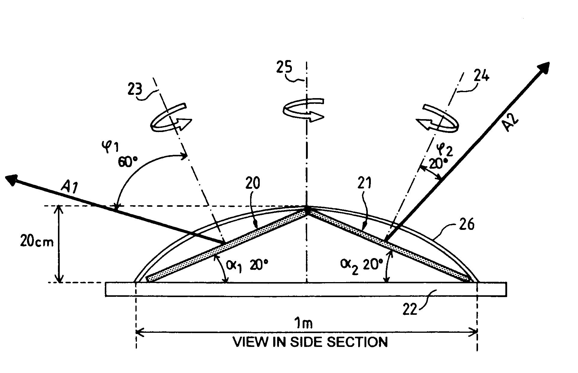
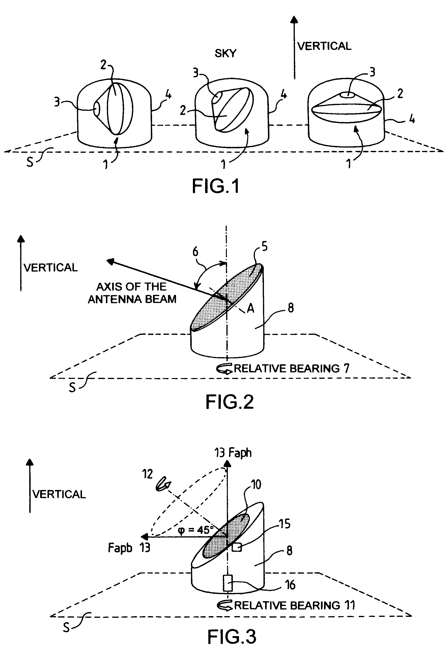
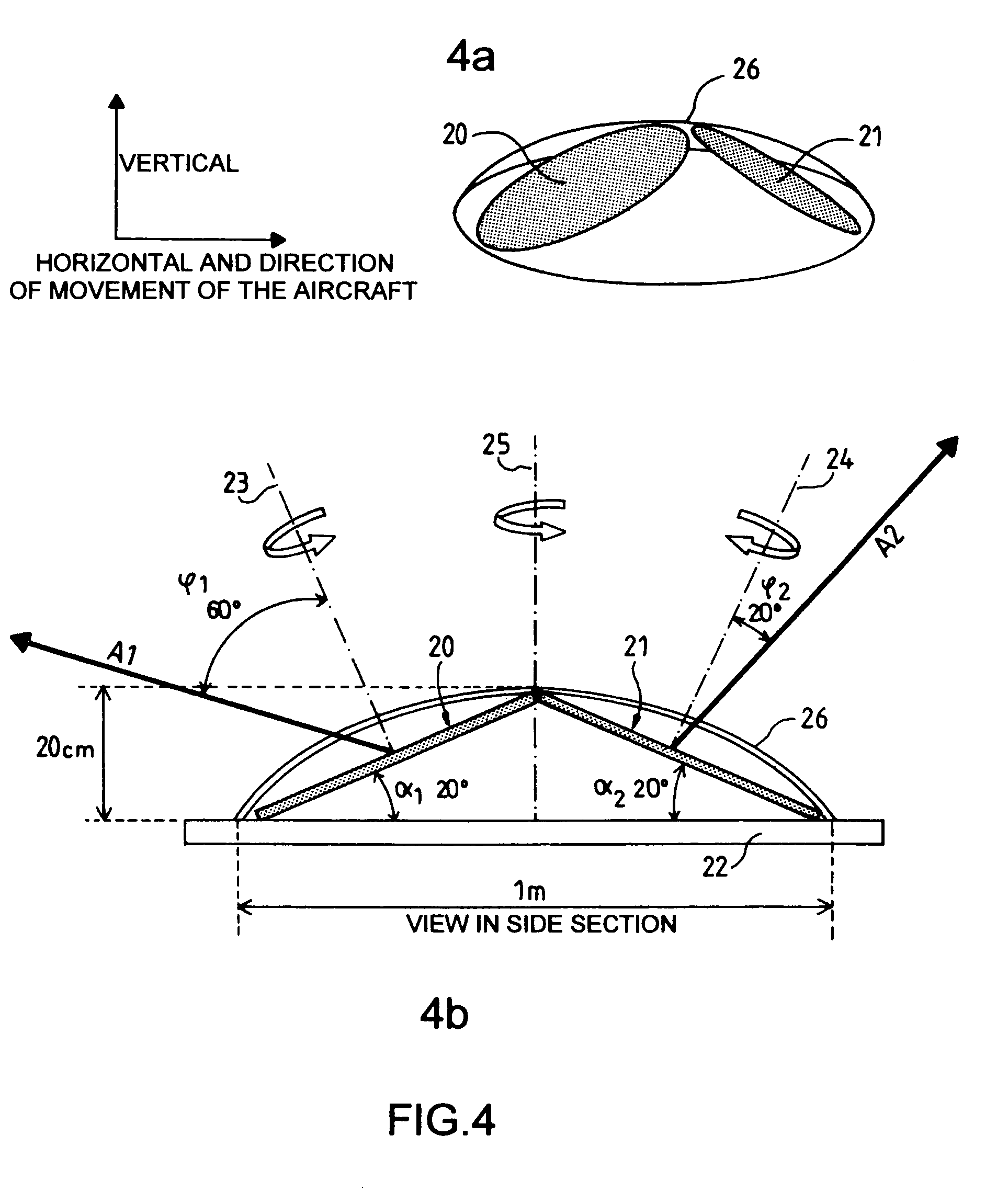
[0022]FIG. 3 is a schematic view of an antenna system comprising a circular, flat antenna 10, with a beam inclined, for example by φ=45° relative to its mechanical axis 12, itself inclined by 45 relative to the vertical to the position. The antenna rotates on its own mechanical axis 12, and a motor 15 enables this rotation. The antenna is associated with a vertical axis of rotation in relative bearing 11 also motor-driven 16. The other elements associated with the antenna and known to those skilled in the art are not shown because they do not play any role in the understanding of the invention.

[0023]According to this arrangement, a rotation of the antenna on its mechanical axis 12 causes the antenna beam 13 to travel on a cone with a 90° vertex angle, the beam passing through all the elevation values from horizontal to vertical (low antenna beam position Fapb and high antenna beam position Faph). The rotation of the antenna on the relative bearing axis enables the beam to be rotated...


PUM


Abstract

An integrated antenna system for telecommunications comprises at least one substantially flat and circular antenna provided with a rotation axis coinciding with its axis, the antenna being fixedly joined to a support itself comprising a rotation axis. The rotation axis of the antenna is inclined by an angle θ relative to the rotation axis of the antenna support and the antenna beam forms an angle φ relative to the rotation axis of the antenna.

Description

RELATED APPLICATION[0001]The present application is based on France Application, and claims priority from Application No. 0410268 filed Sep. 28, 2004, the disclosure of which is hereby incorporated by reference in its entirety.BACKGROUND OF THE INVENTION[0002]1. Field of the Invention[0003]The invention relates especially to an integrated antenna system in space telecommunications for mobile terrestrial stations (Satcom).[0004]It can also be used in related fields such as radars or RF beams whenever the antenna system is in motion relative to its carrier.[0005]In space telecommunications using the C, X, Ku, Ka, Q and other bands, with existing geostationary satellites, the mobile terrestrial stations are supposed to be equipped with an agile antenna automatically aimed at the traffic satellite, whatever its position in the sky (all the elevation angles from 0 to 90°, all the relative bearing angles from 0 to 360°).[0006]In the description, the vertical and horizontal directions are ...

Claims


Application Information

Patent Timeline
Patent Type & Authority Patents(United States)
IPC IPC(8): H01Q1/28
CPCH01Q1/28H01Q3/08
Inventor QUAGLIARO, GILLES
Owner THALES SA
Why Eureka
Try Eureka