
Toroidal transmission

a transmission device and toroidal technology, applied in the direction of control devices, belts/chains/gearrings, mechanical instruments, etc., can solve the problems of occupying additional overall space, unable to provide power range shifting facilities, and requiring additional weigh

Inactive Publication Date: 2008-03-25
GETRAG GETRIEBE & ZAHNRADFABRIK HERMANN HAGENMEYER GMBH & CO KG
View PDF17 Cites 156 Cited by
  • Summary
  • Abstract
  • Description
  • Claims
  • Application Information

AI Technical Summary

Benefits of technology

"The present invention is an improved toroidal transmission for all-wheel drive vehicles that has two output shafts. The transmission includes a first power range shifting means and a second power range shifting means, which have a common clutch. This allows for a \"geared neutral\" function and a longitudinal differential function. The transmission does not require an additional transfer case for dividing the input power between the two output shafts. The use of a common clutch simplifies the overall structure of the transmission. The patent text also mentions the use of variator bypass means, a locking clutch, and a high-range clutch for each drivetrain. These features provide additional benefits and flexibility for the toroidal transmission."

Problems solved by technology

Transfer cases, however, mean additional weight and take up additional overall space.
However, no facility for power range shifting is provided.
Nor can a “geared neutral” be achieved using the transmission.

Method used


Image

  • Toroidal transmission
  • Toroidal transmission
  • Toroidal transmission

Examples


Embodiment Construction

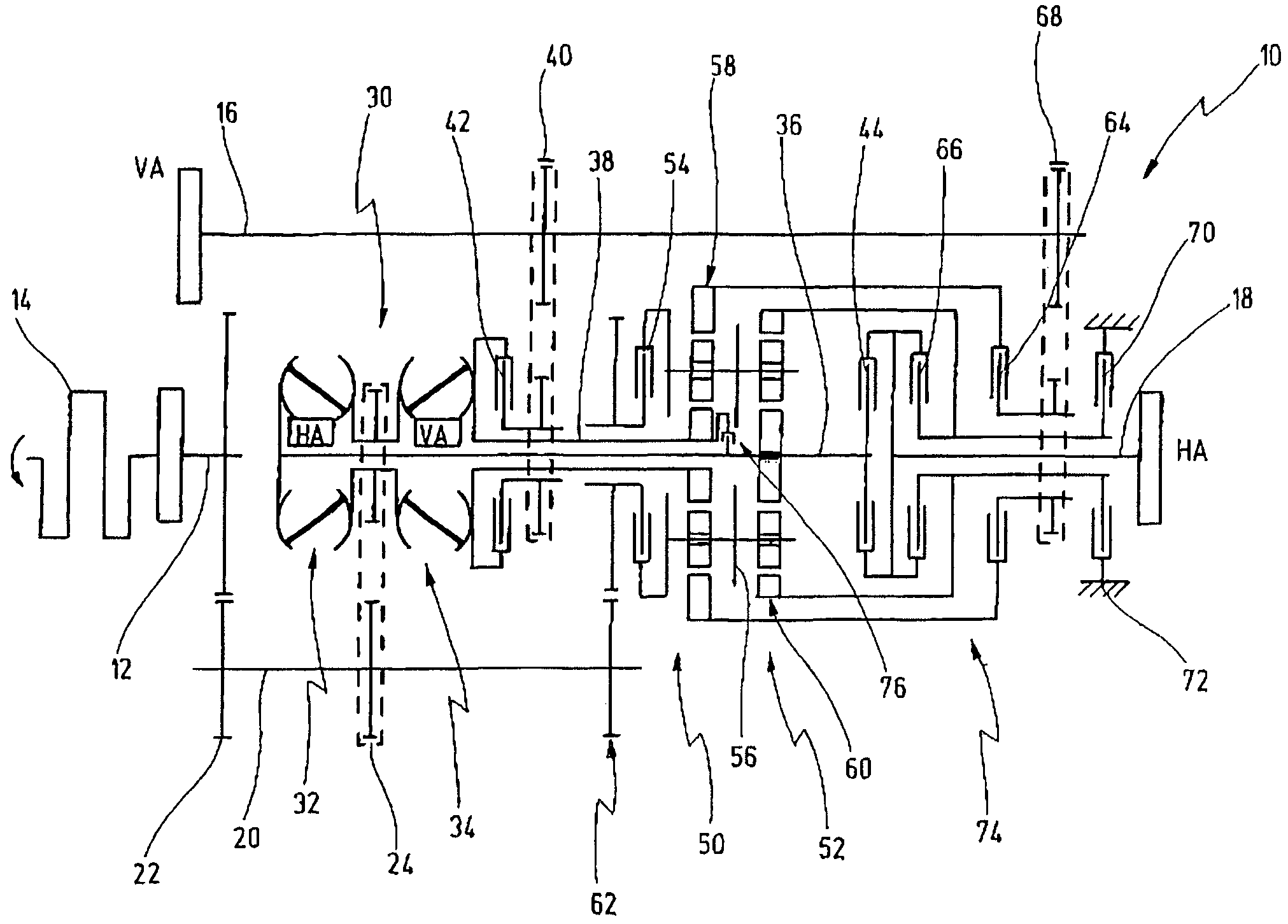
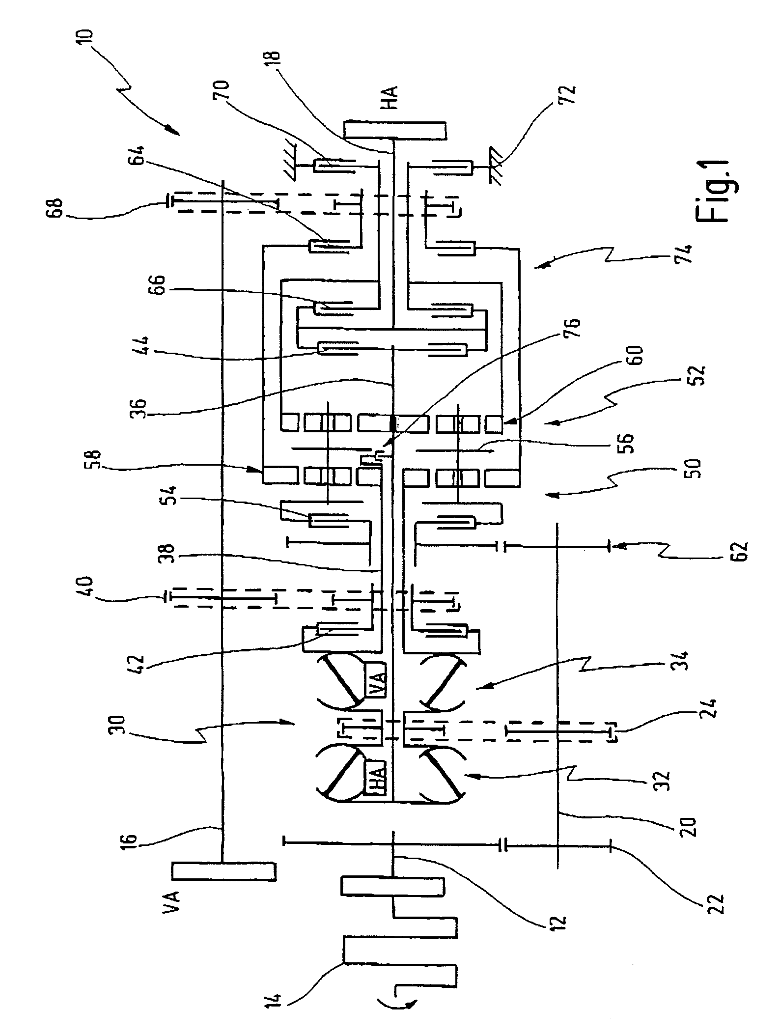
[0045]In FIG. 1 a first embodiment of a toroidal transmission according to the invention is generally denoted by 10.

[0046]The toroidal transmission 10 is designed as a transmission for motor vehicles having an internal combustion engine.

[0047]The toroidal transmission 10 has an input shaft 12, which is connected to an output shaft of an internal combustion engine 14.

[0048]The toroidal transmission 10 furthermore has a first output shaft 16 and a second output shaft 18.

[0049]The first output shaft 16 is parallel to the input shaft 12, serves to drive a front axle VA of the motor vehicle and is usually connected to a front axle differential. The second output shaft 18 serves for connection to a powered rear axle HA of the motor vehicle and is usually connected to a rear axle differential.

[0050]The input shaft 12 of the toroidal transmission 10 is connected to a countershaft 20 by way of a fixed gear train 22. The countershaft 20 is connected to an input shaft of a variator arrangement...


PUM


Abstract

A toroidal transmission, especially for motor vehicles, comprising an input shaft which can be connected to an engine, a first toroidal variator and a second toroidal variator which are connected to the input shaft on the input side. A first output shaft can be connected to the output of the first toroidal variator, and a second output shaft can be connected to the output of the second toroidal variator. The toroidal transmission comprises a first power range shifter for the first toroidal variator and a second power range shifter for the second toroidal variator. The first power range shifter and the second power range shifter have a common clutch.

Description

CROSS-REFERENCE TO RELATED APPLICATIONS[0001]This application is a continuation application of International patent application PCT / EP2005 / 003980 filed Apr. 15, 2005, which claims priority from German patent application DE 10 2004 022 356.BACKGROUND OF THE INVENTION[0002]The present invention relates to a toroidal transmission, especially for motor vehicles, comprising an input shaft which can be connected to an engine, a first toroidal variator and a second toroidal variator which are connected to the input shaft on the input side, a first output shaft which can be connected to the output of the first toroidal variator, and a second output shaft which can be connected to the output of the second toroidal variator.[0003]Such a toroidal transmission is disclosed, for example, by EP 0 743 218 B1.[0004]Toroidal transmissions have long been known in the art. They permit a continuously variable adjustment of the transmission ratio. Toroidal transmissions have hitherto been designed for s...

Claims


Application Information

Patent Timeline
Patent Type & Authority Patents(United States)
IPC IPC(8): F16H37/02F16H37/08
CPCF16H37/086B60K17/348F16H37/0813F16H2037/0886
Inventor GUENTER, RUEHLEWOLF, WALTER
Owner GETRAG GETRIEBE & ZAHNRADFABRIK HERMANN HAGENMEYER GMBH & CO KG
Learn More