Adjustable lift support apparatus

a technology of lift support and adjustable spring, which is applied in the direction of machine supports, rod connections, transportation items, etc., can solve the problems of inconvenient for various users, increased cost of the above-mentioned lift apparatus, and spring loss, etc., and achieves the effect of simple structure and low cost of the present invention

Active Publication Date: 2008-03-18
BENQ CORP
View PDF19 Cites 10 Cited by
  • Summary
  • Abstract
  • Description
  • Claims
  • Application Information

AI Technical Summary

Benefits of technology

[0007]The objective of the present invention is to provide an adjustment lift support apparatus utilizing at least one rack together with a corresponding elastic plate to fix a support of the apparatus at a desired height, such that the external force applied to lift or lower the support is adjustable. Furthermore, according to the present invention, the adjustable lift support apparatus won't lose its function after being used for a span of time. Moreover, the cost of the present invention is lower and the structure is simpler than the prior art.
[0010]Accordingly, the adjustable lift support apparatus of the present invention utilizes at least one rack together with a corresponding elastic plate to fix a support of the apparatus at a desired height, such that the external force applied to lift or lower the support is adjustable. Furthermore, according to the present invention, the adjustable lift support apparatus won't lose its function after being used for a span of time. Moreover, the cost of the present invention is lower and the structure is simpler than the prior art.

Problems solved by technology

However, because the torsion of the springs of the above-mentioned lift apparatus always maintains constant and cannot be adjusted, it is inconvenient for various users.
Furthermore, after the lift apparatus is used for a span of time, the spring may lose its elasticity due to the fatigue.
Moreover, the cost of the above-mentioned lift apparatus is more expensive, and the structure is more complicated.

Method used


Image

  • Adjustable lift support apparatus
  • Adjustable lift support apparatus
  • Adjustable lift support apparatus

Examples


Embodiment Construction

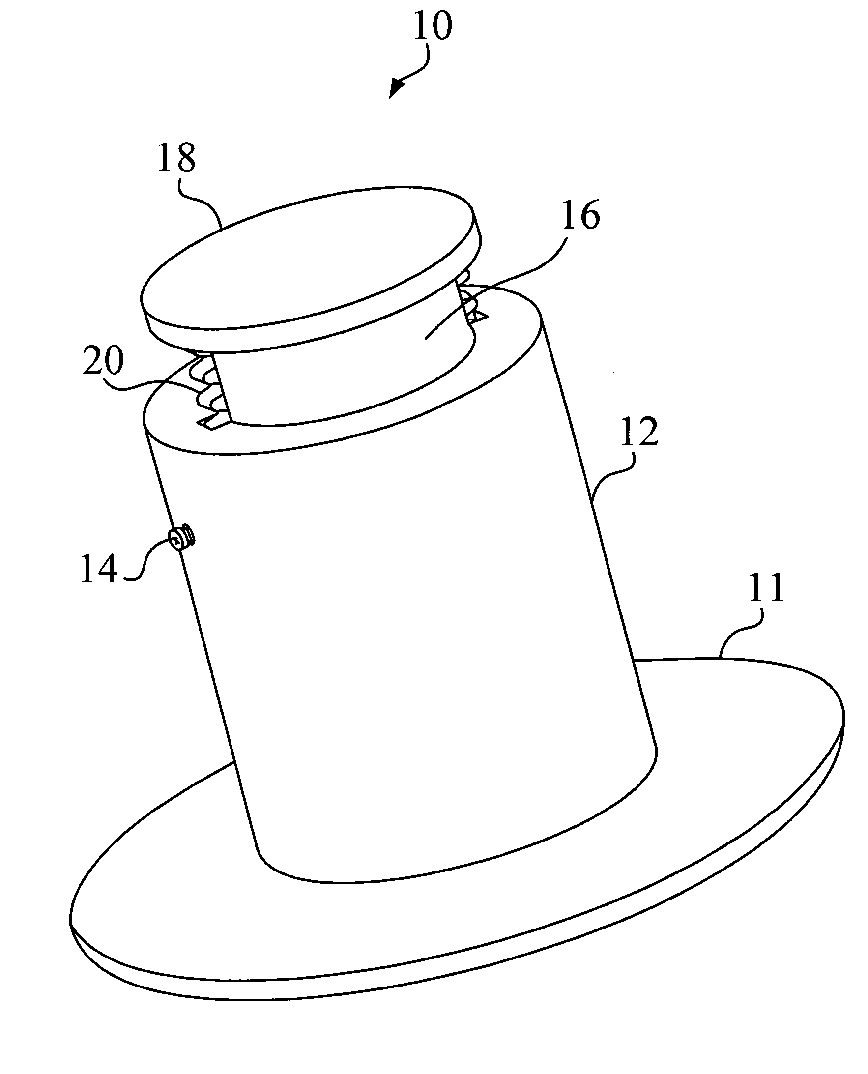
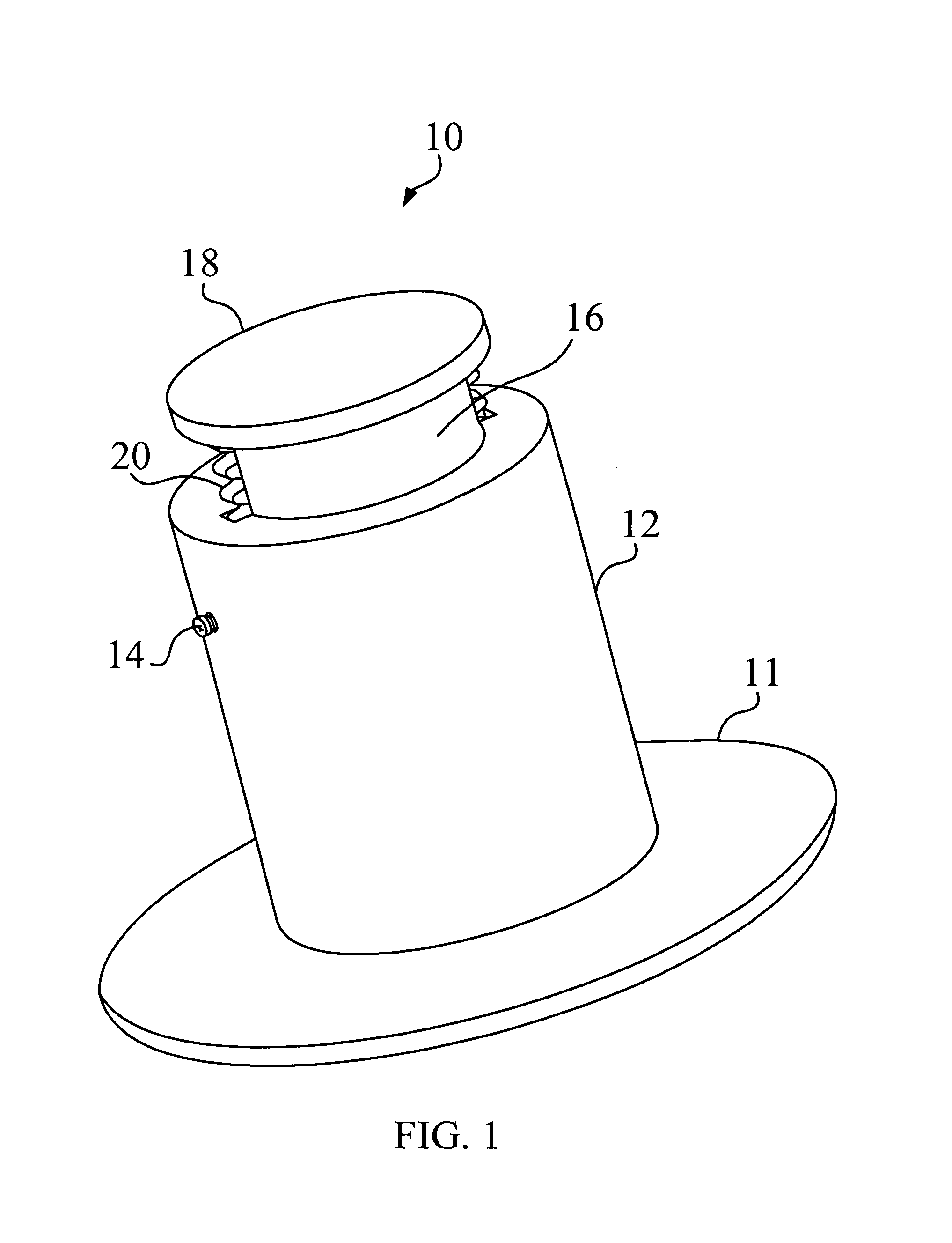
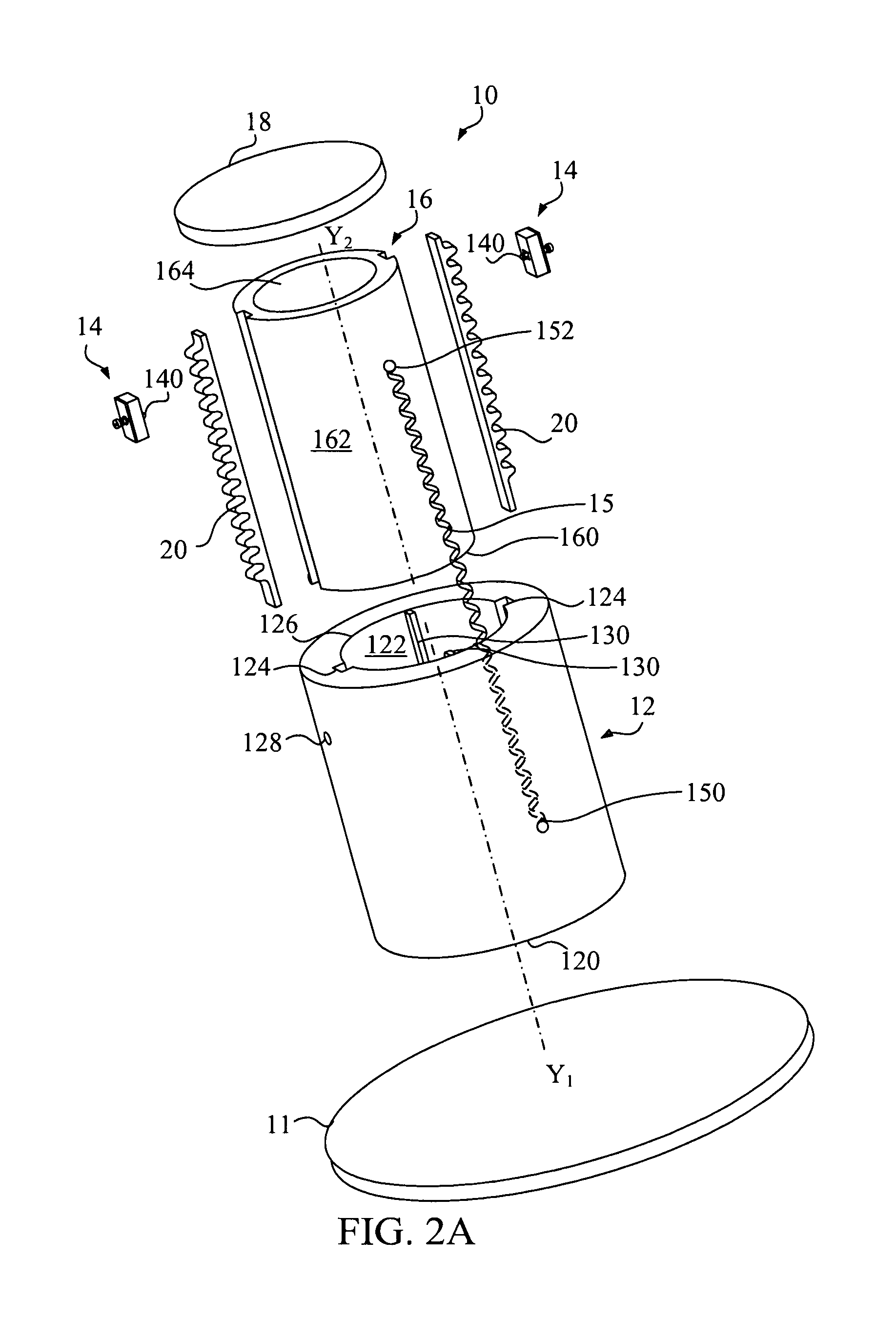
[0020]Referring to FIGS. 1, 2A and 2B, FIG. 1 is an outside view illustrating an adjustable lift support apparatus 10 according to a preferred embodiment of the present invention. FIGS. 2A and 2B are exploded views illustrating the adjustable lift support apparatus 10 shown in FIG. 1. The adjustable lift support apparatus 10 includes a base 11, a sleeve 12, at least one meshing device 14, a shaft 16, and a support 18. For practical application, the sleeve 12 and the shaft 16 both are substantially pillar-shaped or arc-shaped. In this embodiment, the sleeve 12 and the shaft 16 both are cylinders, and the adjustable lift support apparatus 10 includes two meshing devices 14.

[0021]As shown in FIGS. 2A and 2B, the sleeve 12 is attached onto the base 11 via a tail end 120 of the sleeve 12 and has an inner surface 122. At least one groove 124 is formed on the inner surface 122 from a head end 126 of the sleeve 12 along a first axial direction Y1. In this embodiment, two grooves 124 are for...


PUM


Abstract

An adjustable lift support apparatus includes a base, a sleeve attached onto the base, at least one meshing device, a shaft, and a support attached at the shaft. At least one groove is formed on an inner surface of the sleeve along a first axial direction. Each meshing device corresponds to one of the at least one groove and includes a flexible protrusion. The shaft is inserted into the sleeve. At least one rack is provided on an outer surface of the shaft along a second axial direction, such that the flexible protrusion of the meshing device is meshed between two neighboring teeth of the at least one rack. The support is lifted or lowered by an external force to make each of the at least one rack move with respect to the flexible protrusion of the corresponding meshing device, so as to adjust the height of the support.

Description

BACKGROUND OF THE INVENTION[0001]1. Field of the Invention[0002]The present invention relates to an adjustable lift support apparatus, and more particularly to an adjustable lift support apparatus capable of preventing the function from failure after being used for a span of time.[0003]2. Description of the Prior Art[0004]Recently, flat panel displays have become increasingly popular substitutes for projection devices and cathode ray tube (CRT) displays. The flat panel display, e.g. liquid crystal display (LCD), is typically mounted on a lift apparatus to be lifted or lowered.[0005]Ideally, the height of the flat panel display can be adjusted for optimum viewing. Various prior arts with regard to the lift apparatus have been used, such as mechanical ball track with constant force spring, mechanical linkages with springs, and so on. However, because the torsion of the springs of the above-mentioned lift apparatus always maintains constant and cannot be adjusted, it is inconvenient fo...

Claims


Application Information

Patent Timeline
Patent Type & Authority Patents(United States)
IPC IPC(8): F16M11/00
CPCF16M11/28F16M2200/028Y10T403/32475Y10T403/7077Y10T403/32467
Inventor SHE, WEI-SHIN
Owner BENQ CORP
Why Eureka
Try Eureka