
Quick-disconnect coupler

a quick-disconnect and coupler technology, applied in the field ofcouplers, can solve the problems of ten or more separate components, difficult to meet the needs of customers,

Inactive Publication Date: 2008-03-18
PACKHAM TRENT
View PDF3 Cites 60 Cited by
  • Summary
  • Abstract
  • Description
  • Claims
  • Application Information

AI Technical Summary

Benefits of technology

"The invention is an improved quick-dis / connect coupler for connecting fluid-carrying tubes. The coupler has a reduced component count, a less tortuous flow path, and no springs or other obstructions directly in the fluid flow path. It includes a female coupler module and a male coupler module with a female coupler housing and a male coupler housing. The female coupler housing has a connector for connecting to a tube and a stopcock valve with a torsion spring and an o-ring. The male coupler housing has a connector for connecting to a tube and a stopcock valve with a torsion spring. The couplers can be easily disconnected and reconnected. The technical effects of this invention are improved efficiency, reliability, and reduced manufacturing and assembly costs."

Problems solved by technology

One disadvantage of poppet valves is that they result in tortuous fluid flow paths.
Another serious shortcoming of commercially available quick-dis / connect couplers is that they are constructed of fifteen or more separate components.
The high component count causes increased manufacturing and assembly cost, increased inventory requirements, and reduced product reliability.

Method used


Image

  • Quick-disconnect coupler
  • Quick-disconnect coupler
  • Quick-disconnect coupler

Examples


Embodiment Construction

[0018]The invention will be understood more fully from the detailed description given below and from the accompanying drawings of embodiments of the invention which, however, should not be taken to limit the invention to the specific embodiments described, but are for explanation and understanding only.

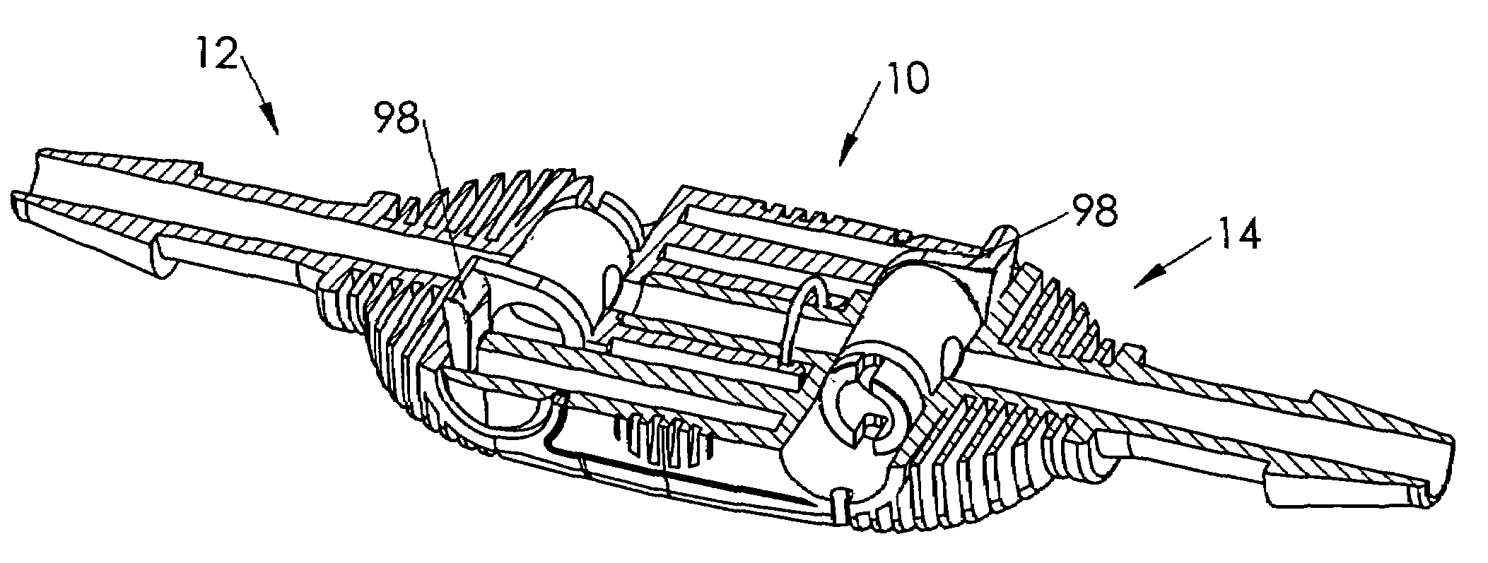
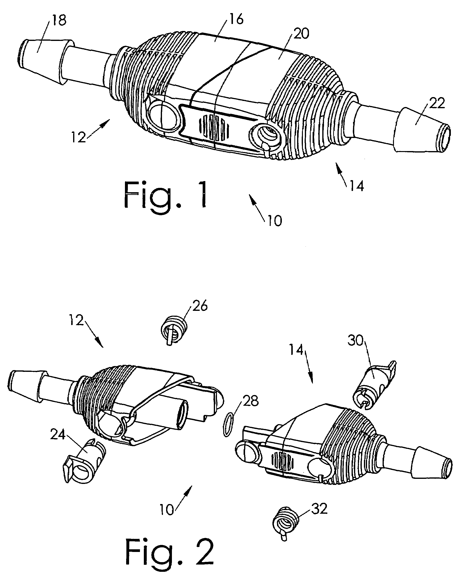
[0019]FIG. 1 illustrates a quick-dis / connect coupler 10 according to one embodiment of this invention. The quick-dis / connect coupler includes a female coupler module 12 and a male coupler module 14.

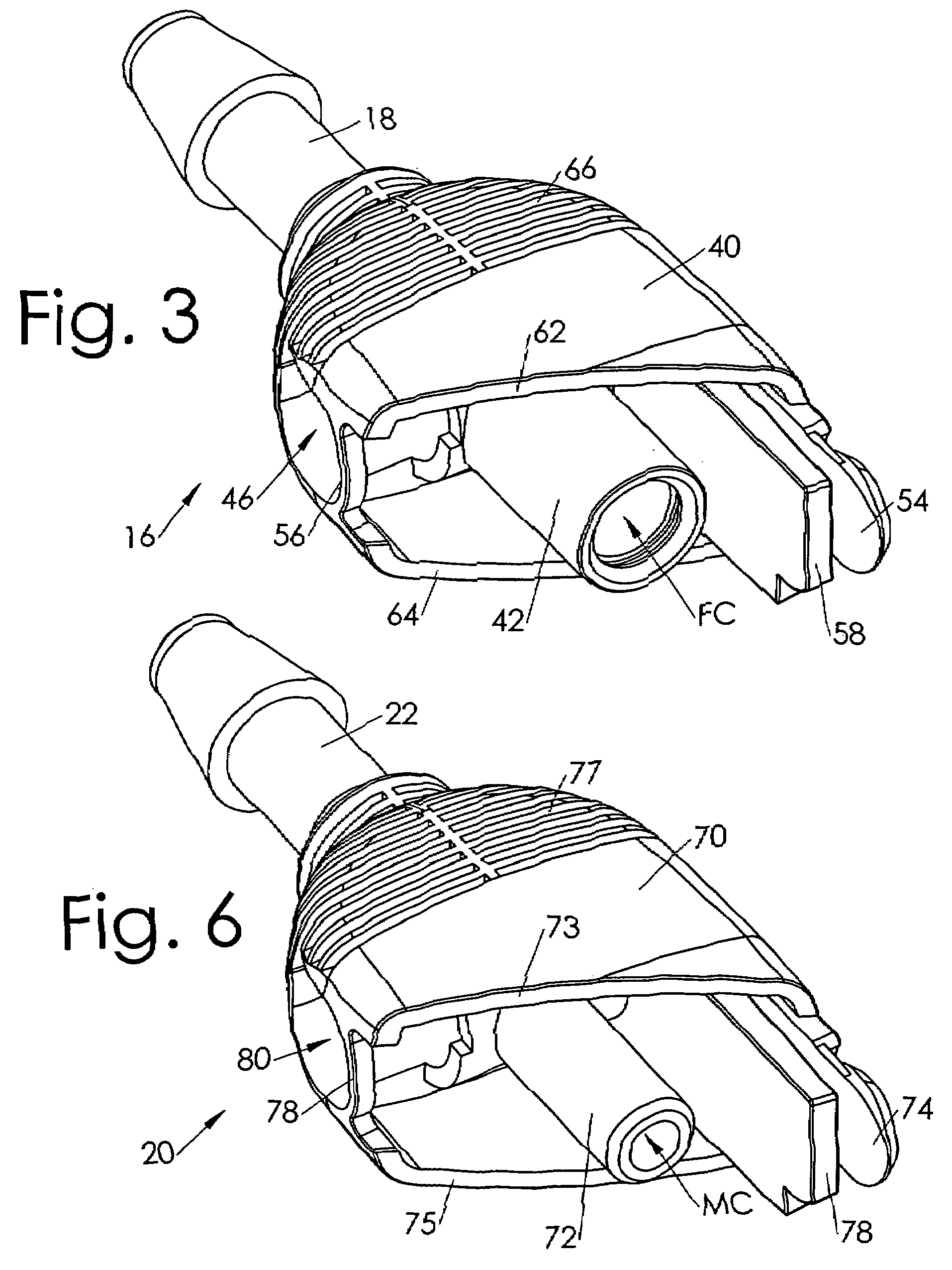
[0020]The female coupler module includes a female coupler housing 16 which has a connector 18 for connecting to a tube (not shown). The male coupler module includes a male coupler housing 20 which has a connector 22 for connecting to a tube (not shown). Although the tube connectors are, for convenience, illustrated as being of the barbed type commonly used with flexible tubing, any sort of connector can be used in practicing this invention.

[0021]FIG. 2 illustrates the quick-dis / connect coup...


PUM


Abstract

A quick-dis / connect coupler including two coupler modules, male and female. Each includes a housing. At least one includes a stopcock valve. The housing bodies are configured such that, as they are engaged / disengaged, each automatically opens / closes the other's stopcock valve. The complete coupler may include seven or fewer components, with five or fewer skus among them. The coupler provides a straight-through, laminar fluid flow path with no dead zones and essentially zero occlusion, and has no springs or other such components inside the fluid flow. The coupler uses inexpensive injection molding and snap-fit components which are dual-latched. The valve-closing springs also provide positive eject force upon disengagement of the coupler.

Description

RELATED APPLICATION[0001]This application claims filing priority benefit of a provisional application 60 / 802,917 entitled “Medical Device Couplers” filed May 23, 2006 by this inventor, which is incorporated herein by reference.BACKGROUND OF THE INVENTION[0002]1. Technical Field of the Invention[0003]This invention relates generally to couplers for connecting fluid-carrying tubes, and more specifically to an improved quick-dis / connect coupler of the type having two mating components, each for coupling to a respective one of two tubes to be connected.[0004]2. Background Art[0005]A variety of quick-dis / connect couplers are known in many industries for use in connecting tubes, hoses, and the like. Quick-dis / connect couplers are used to connect and disconnect tubes, hoses, pipes, and other fluid-carrying implements (hereafter generically “tubes”). Quick-dis / connect couplers are not merely connectors; their function is not merely to mechanically connect the tubes. They also serve to inter...

Claims


Application Information

Patent Timeline
Patent Type & Authority Patents(United States)
IPC IPC(8): F16L37/34
CPCF16L37/32F16L37/373Y10T137/87949Y10T137/87957
Inventor PACKHAM, TRENT
Owner PACKHAM TRENT
Learn More