
Method for operating a loom

a technology of looms and looms, applied in the field of looms, can solve problems such as problems such as synchronization

Active Publication Date: 2008-03-11
PICANOL NV
View PDF23 Cites 7 Cited by
  • Summary
  • Abstract
  • Description
  • Claims
  • Application Information

AI Technical Summary

Benefits of technology

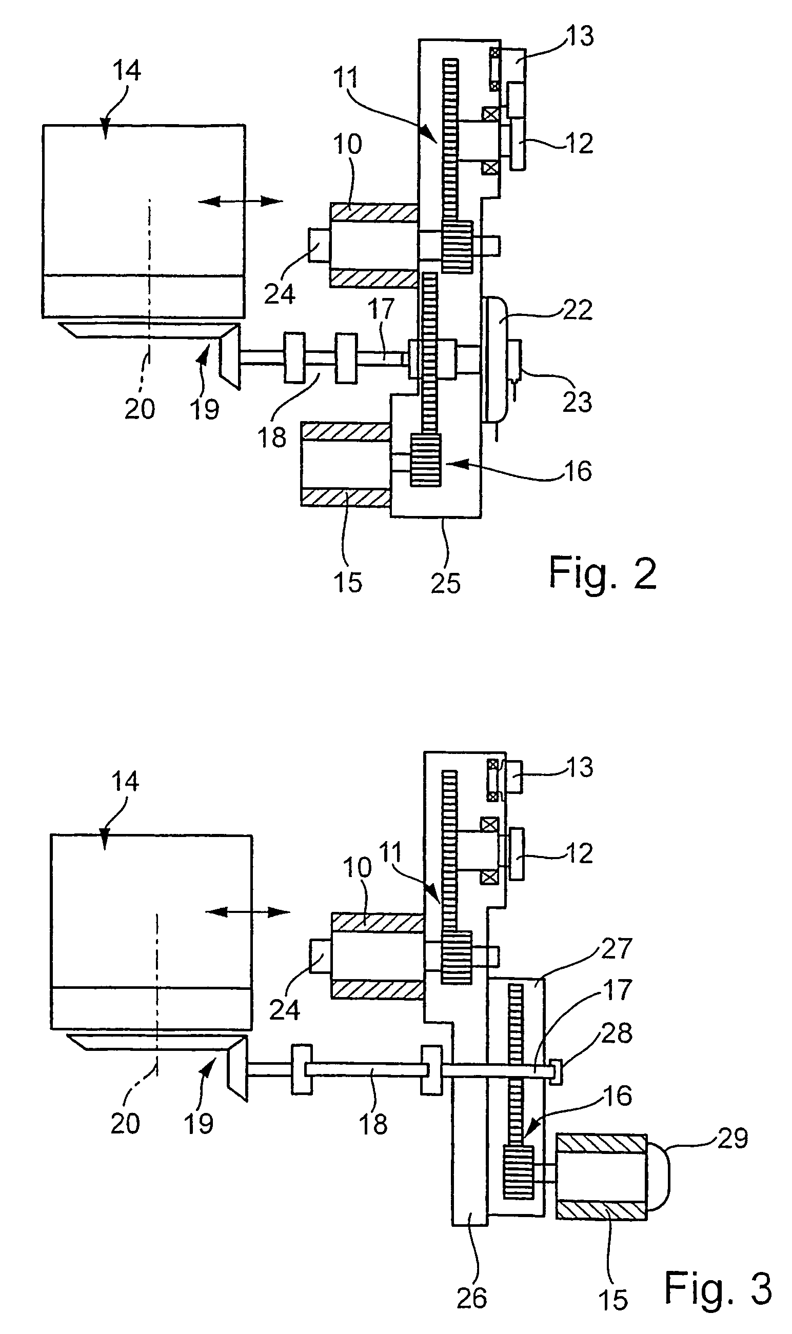
[0016]In a simple embodiment, which requires virtually no changes to be made in a loom, the drive motor of the shedding means is mounted on a frame of the loom and is connected to the drive elements of the shedding means via a resilient coupling element. The resilient coupling element is appropriate at least in order not to transmit vibration from the shedding means to the other elements of the loom, and vice versa.

Problems solved by technology

This synchronization presents problems, since the main shaft rotational speed changes.

Method used


Image

  • Method for operating a loom
  • Method for operating a loom
  • Method for operating a loom

Examples


Embodiment Construction

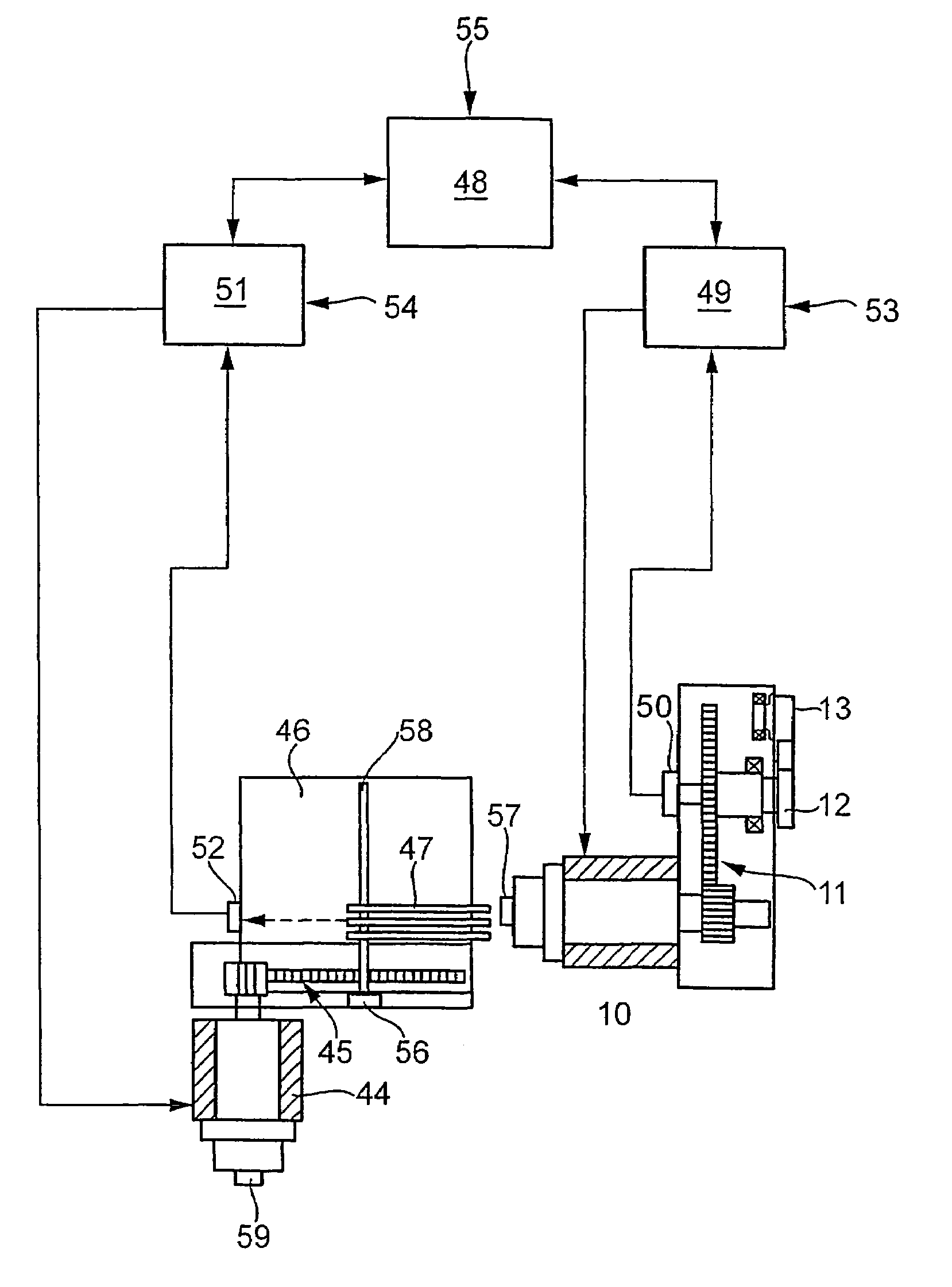
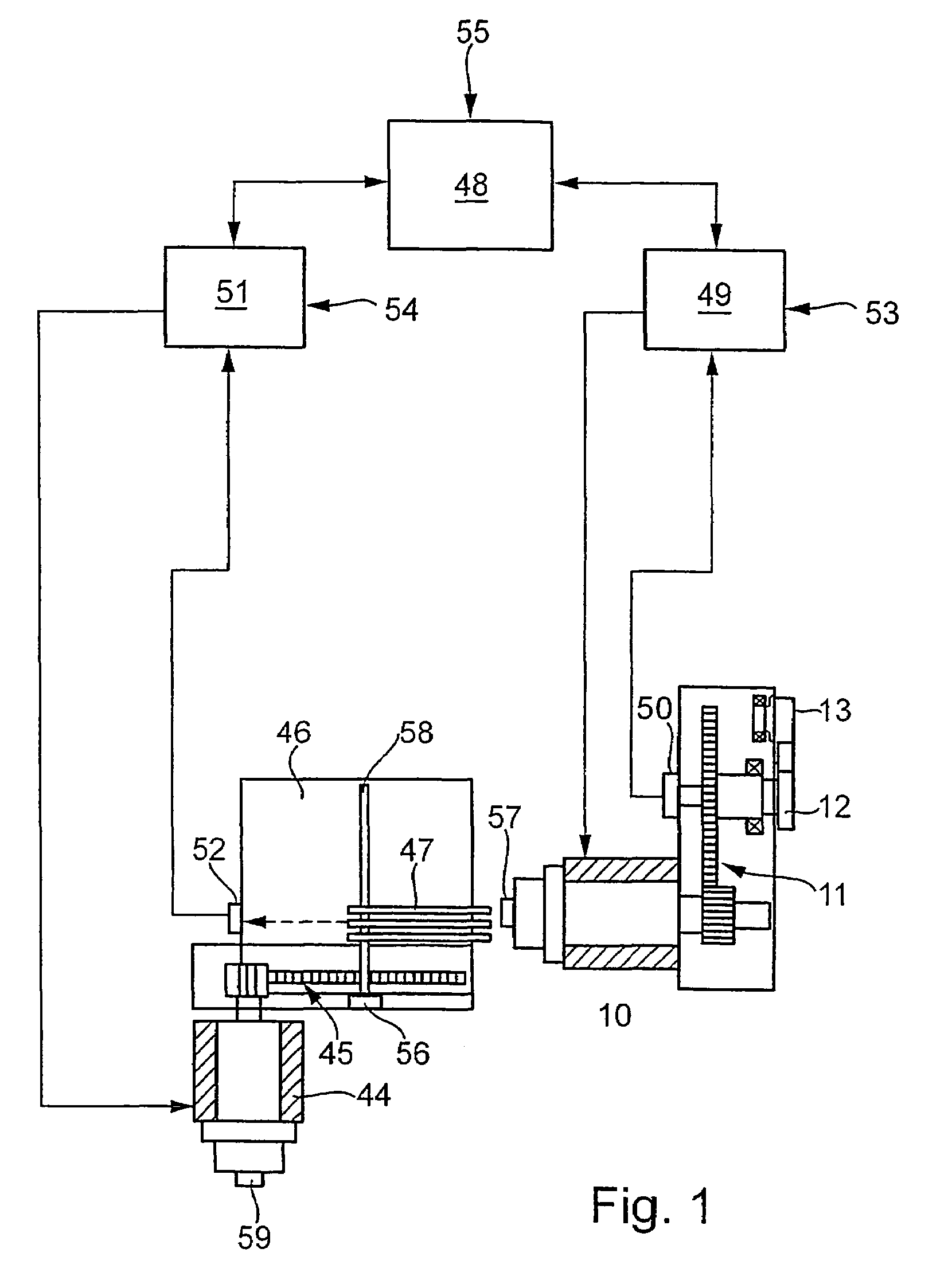
[0027]A first drive motor 10, via a gear stage 11, drives a drive shaft 12 for a batten 13. A second drive motor 44, via a gear stage 45, drives a shedding mechanism 46, embodied for instance as a dobby, which is connected to heddle shafts, not shown, via rod assembly 47.

[0028]During one weaving cycle, the shaft 12, which is typically called the main shaft, executes a rotation of 360°. At 0° or 360°, the weaving reed located on the batten 13 beats up an inserted weft yarn. The heddle shafts driven, that is, raised and lowered, by the shedding mechanism 46 and the rod assembly 47, form a shed into which a weft yarn is inserted. After the weft insertion, the shed is changed, by raising and lowering other heddle shafts, after which the next weft yarn is inserted. The change of the shed is done for instance even before the inserted weft yarn has been finally beaten-up. In this process, the warp yarns of the heddle shafts that are moving upward cross with the warp yarns of the heddle sha...


PUM


Abstract

A loom having a first drive motor (10), which for instance drives a batten (13), and having at least one second drive motor (44), which drives a dobby (46), is provided with a control and regulating device (48), which forms a rotational angle course for a virtual synchronization shaft of the loom and communicates such rotational angle course to respective control and regulating units (49, 51) of each of the drive motors (10, 44), which synchronize the drive motors in at least one angular position relative to the virtual synchronization shaft.

Description

BACKGROUND OF THE INVENTION[0001]A. Field[0002]The invention relates to a method for operating a loom, having a first drive motor which drives a first element, such as a batten, and at least a second drive motor which drives a second element, such as a shedding mechanism.[0003]B. Related Art[0004]In looms, the motions of the individual elements must be chronologically adapted to one another. To achieve this chronological adaptation when independent drive motors are used, it is known to detect the rotational angle position of a main shaft, which in particular drives a batten, and to synchronize the drive motor or drive motors of the other elements with these rotational angle positions. This synchronization presents problems, since the main shaft rotational speed changes. Before the beating-up of an inserted weft yarn, the rotational speed of the main shaft decreases. When the batten with the weaving reed reaches the rearward position, the rotational speed of the main shaft increases....

Claims


Application Information

Patent Timeline
IPC IPC(8): D03D51/00D03D51/02D03D51/28D03C13/00
CPCD03C1/146D03D51/02D03D51/005
Inventor SAMPERS, DIRK
Owner PICANOL NV
Learn More