
Method and apparatus for machine-vision

a machine vision and machine vision technology, applied in the field of machine vision, can solve the problems of increasing the cost, complexity, and the need for calibration, and the impracticality of stereo based systems for industrial applications, and reducing the accuracy of machine vision

Active Publication Date: 2008-02-26
ROBOTICVISIONTECH INC
View PDF46 Cites 77 Cited by
  • Summary
  • Abstract
  • Description
  • Claims
  • Application Information

AI Technical Summary

Benefits of technology

"The patent describes a method and system for machine-vision of objects using images captured by multiple cameras. The method involves identifying features on the object and using these features to create a system of equations and unknowns. The system of equations can then be solved to determine the position of the object. The system can also automatically determine the number of additional views needed to capture the object based on the number of cameras and the type of physical relationship between the features. The system can also use pre-runtime or runtime environments to compute the local model and determine the position of the object. The technical effects of this invention include improved accuracy and efficiency in object recognition and position estimation."

Problems solved by technology

Many drawbacks exist that render stereo based systems impractical for industrial applications.
The measurement error in such systems increases rapidly in response to image feature detection errors; these systems also require exactly known geometrical relationships between camera pairs.
Furthermore stereo methods require the use of at least double the number of cameras which drives up the cost, complexity and the need for calibration.
Drawbacks of such attempts include the need for expensive specialized sensors as opposed to use of standard off-the-shelf hardware, the need for knowledge of exact geometric relationships between all elements of the system including cameras and lasers, susceptibility to damage or misalignment when operating in industrial environments as well as posing of a potential safety hazard when laser light sources are deployed in proximity of human operators.
In practice such a requirement is cumbersome and time-consuming to fulfill and difficult to automate.
One source for such data is object Computer Aided Design (CAD) models; however, such data files are often not readily available.
This process is difficult and error prone especially in the case of large objects with features that are scattered in different regions.

Method used


Image

  • Method and apparatus for machine-vision
  • Method and apparatus for machine-vision
  • Method and apparatus for machine-vision

Examples


Embodiment Construction

[0033]In the following description, certain specific details are set forth in order to provide a thorough understanding of various disclosed embodiments. However, one skilled in the relevant art will recognize that embodiments may be practiced without one or more of these specific details, or with other methods, components, materials, etc. In other instances, well-known structures associated with robotic systems, robots, computing systems, processors and / or image sensors have not been shown or described in detail to avoid unnecessarily obscuring descriptions of the embodiments.

[0034]Unless the context requires otherwise, throughout the specification and claims which follow, the word “comprise” and variations thereof, such as, “comprises” and “comprising” are to be construed in an open, inclusive sense, that is as “including, but not limited to.”

[0035]Reference throughout this specification to “one embodiment” or “an embodiment” means that a particular feature, structure or character...


PUM


Abstract

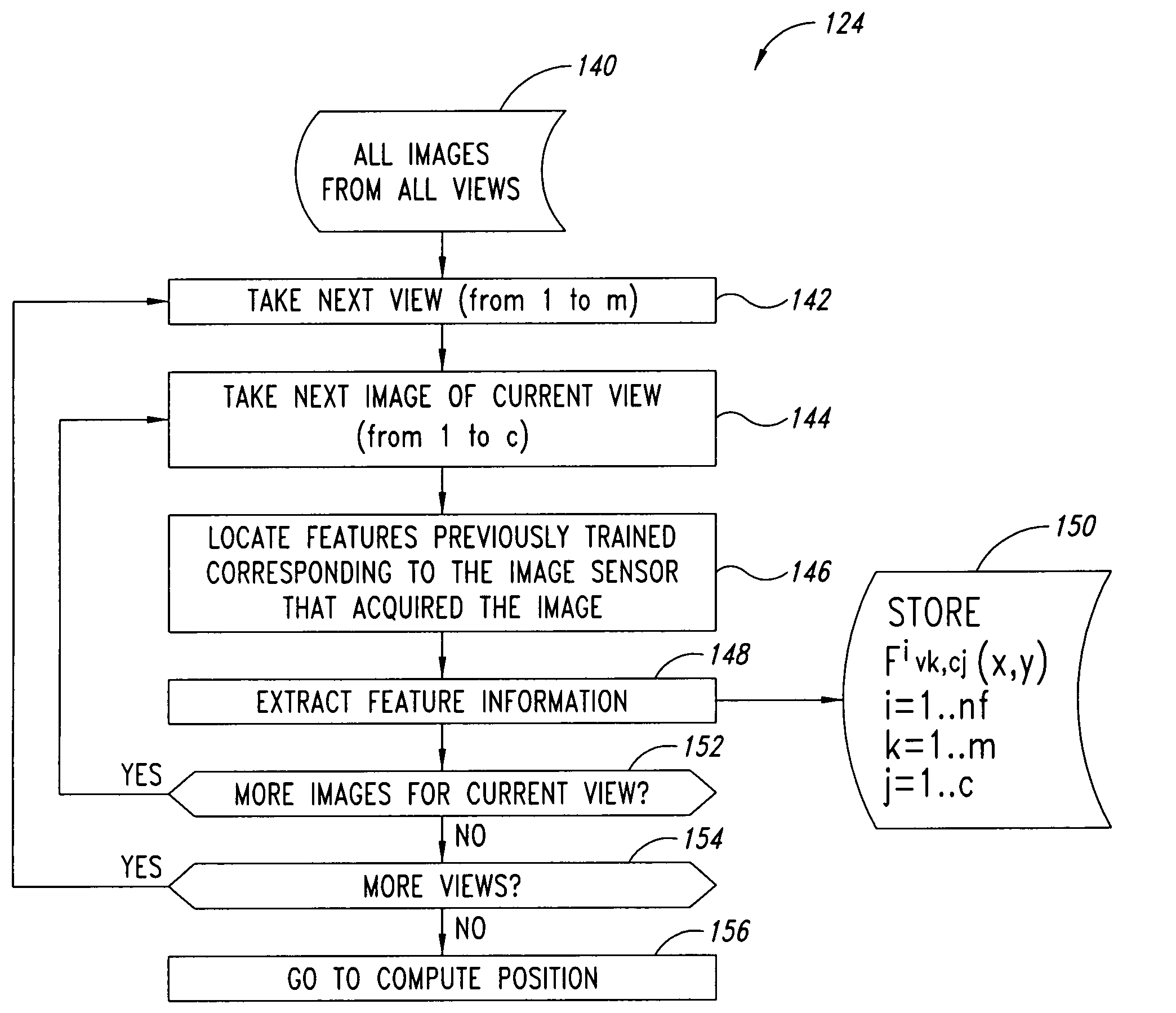
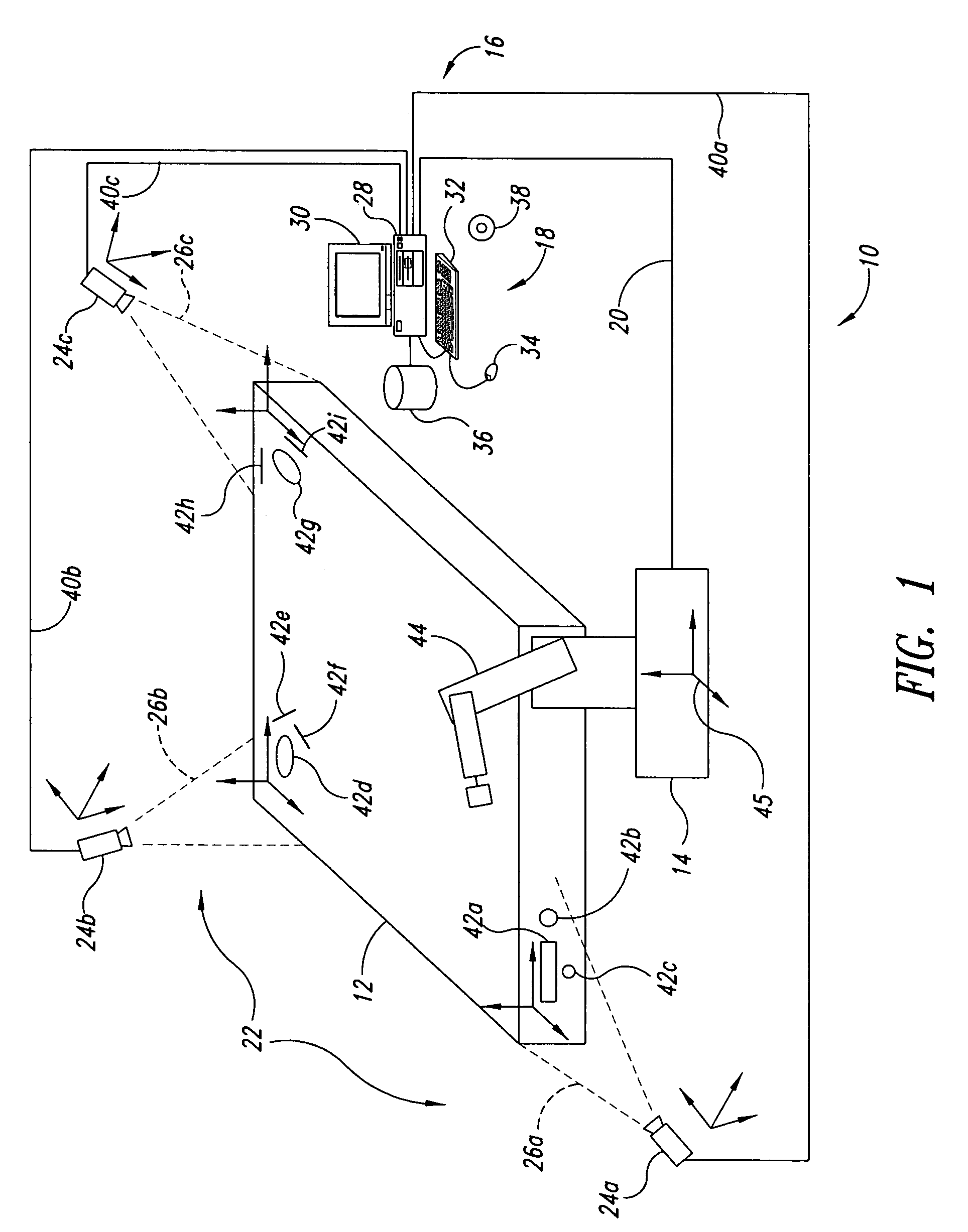
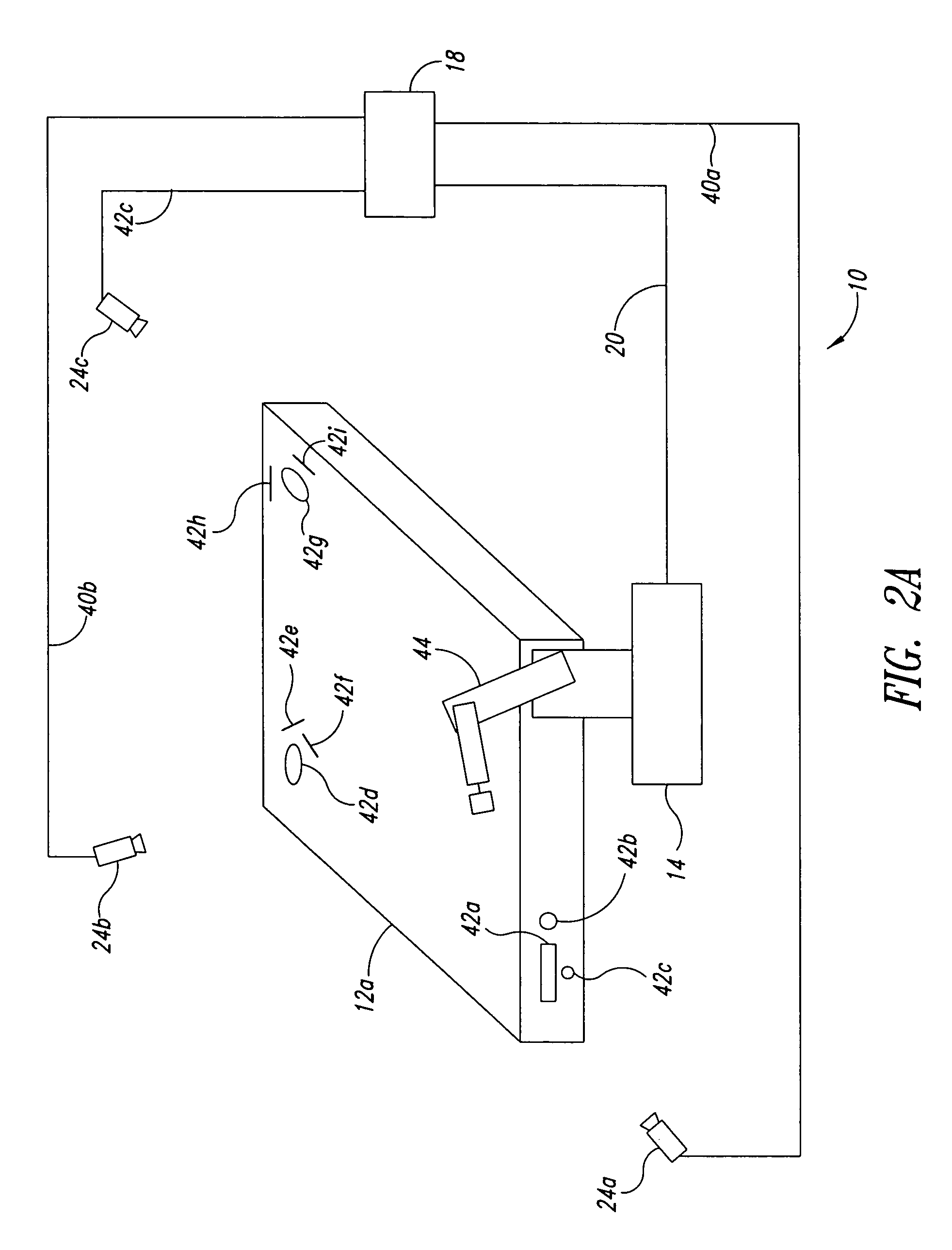
A system and method facilitate machine-vision, for example three-dimensional pose estimation for target objects, using one or more images sensors to acquire images of the target object at one or more positions, and to identify features of the target object in the resulting images. A set of equations is set up exploiting invariant physical relationships between features such as constancy of distances, angles, and areas or volumes enclosed by or between features. The set of equations may be solved to estimate a 3D pose. The number of positions may be determined based on the number of image sensors, number of features identified, and / or number of known physical relationships between less than all features. Knowledge of physical relationships between image sensors and / or between features and image sensors may be employed. A robot path may be transformed based on the pose, to align the path with the target object.

Description

CROSS-REFERENCE TO RELATED APPLICATIONS[0001]This application claims benefit under 35 U.S.C. 119(e) to U.S. provisional application Ser. No. 60 / 587,488, filed Jul. 14, 2004.BACKGROUND OF THE INVENTION[0002]1. Field of the Invention[0003]This disclosure relates to the field of machine vision, which may be useful in robotics, inspection or modeling.[0004]2. Description of the Related Art[0005]Increasingly more manufacturing operations are performed with the aid of industrial robots. Robots that had traditionally been used as blind motion playback machines are now benefiting from intelligent sensor-based software to adapt to changes in their surroundings. In particular, the use of machine vision has been on the rise in industrial robotics. A typical vision guided robotic system analyzes image(s) from one or more cameras to arrive at such information as the position and orientation of a workpiece upon which the robotic tool is to operate.[0006]Early implementations of vision guided robo...

Claims


Application Information

Patent Timeline
Patent Type & Authority Patents(United States)
IPC IPC(8): G06K9/00G06V10/24
CPCG06K9/32G06T7/0018G06T7/0044G06T7/0046G06T7/0075G06T7/80G06T7/74G06T7/75G06T7/593G06V10/24
Inventor BOCA, REMUS FHABIBI, BABAKSAMETI, MOHAMMADPESCARU, SIMONA
Owner ROBOTICVISIONTECH INC
Learn More