
Method and apparatus for remote control vehicle identification

a technology for remote control vehicles and identification methods, applied in sport apparatus, burglar alarm mechanical actuation, instruments, etc., can solve problems such as lasers posing a potential hazard to users, limited number of cars at the same time, and obvious human error and cheating in systems, so as to avoid most broadcast conflicts

Active Publication Date: 2008-02-26
LE MICHAEL Q
View PDF12 Cites 42 Cited by
  • Summary
  • Abstract
  • Description
  • Claims
  • Application Information

AI Technical Summary

Benefits of technology

This solution provides accurate, efficient, and scalable vehicle tracking and identification, allowing for unlimited concurrent participants and enabling remote races across different tracks without the need for pre-registration or extensive infrastructure, while minimizing data collisions and power consumption.

Problems solved by technology

A vexing problem for such racing which has also been around since racing first began is the tracking of the vehicles in the race.
This system was obviously prone to human error and cheating.
However, this system has an inherent problem in that only a limited number of cars can be run at the same time because of the spacing required for the lanes and the length of the antenna.
Another drawback to this system is that the laser poses a potential hazard to the users.
However, a problem with this system is that the transponder must be mounted on the car with a direct line of sight to the receivers which may be difficult in some vehicles.
Additionally, because infrared detection is used, the background light radiation (since light produces infrared waves) can degrade the performance of the system.
The transponders also require power from the vehicle to which they are mounted and are relatively large.
This precludes the use of this system in small scale vehicles such as the 1 / 64 scale ZipZaps which have small capacity batteries that cannot tolerate the extra power drain nor the extra weight of the transponder.
It has the same drawbacks relating to the size of the transponder as the previous system and the current draw which can slow the car or decrease its range.
It is, of course, not well adapted to small battery powered or model racing due to the continuous current draw of the transceiver.
Further, the required separation of frequencies on the radio band used, limits the number of participants that can be tracked.
However, this system can only detect a certain number of limited frequencies.
In addition to the problems related to limited participant number and power drain, none of the systems noted above provide a means to remotely identify the vehicle being tracked.
Consequently, the race participants must go through the time consuming process of registering at each race event for each race around the given track.
Because each individual track has their own identifiers, it precludes having remote races with remote participants competing around different tracks since there is no common manner to identify the cars on the tracks.

Method used


Image

  • Method and apparatus for remote control vehicle identification
  • Method and apparatus for remote control vehicle identification
  • Method and apparatus for remote control vehicle identification

Examples


Embodiment Construction

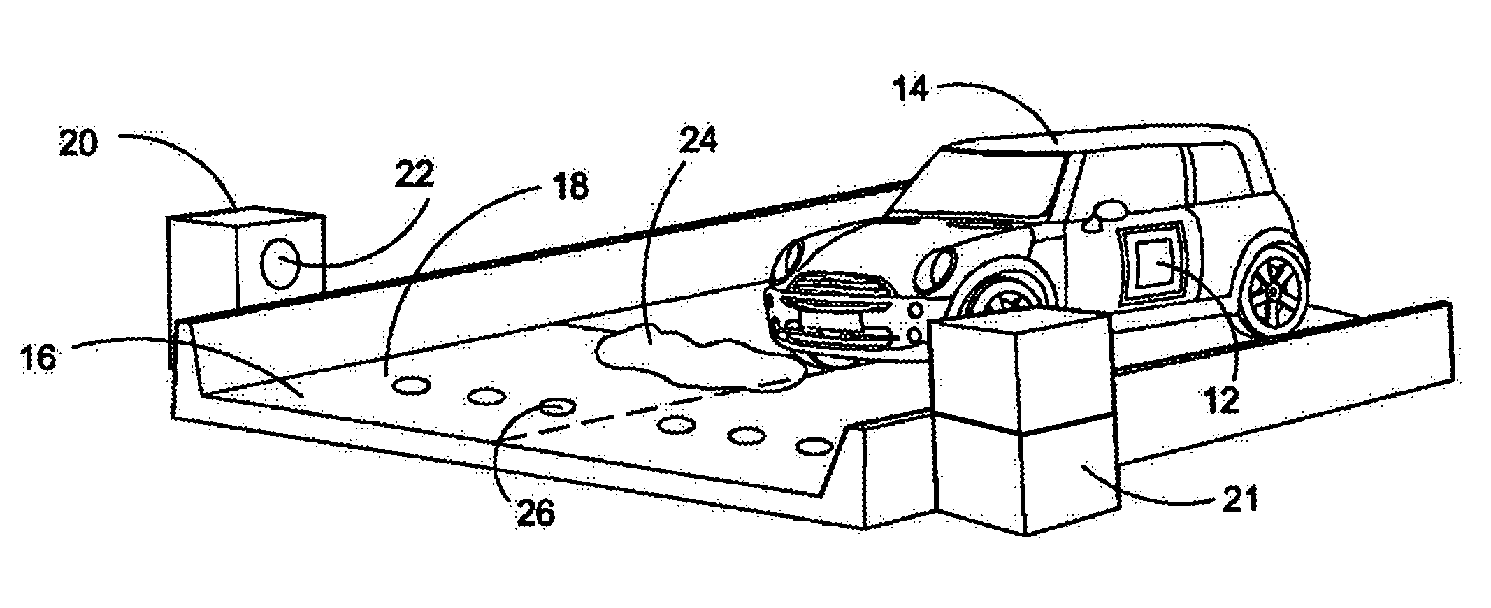
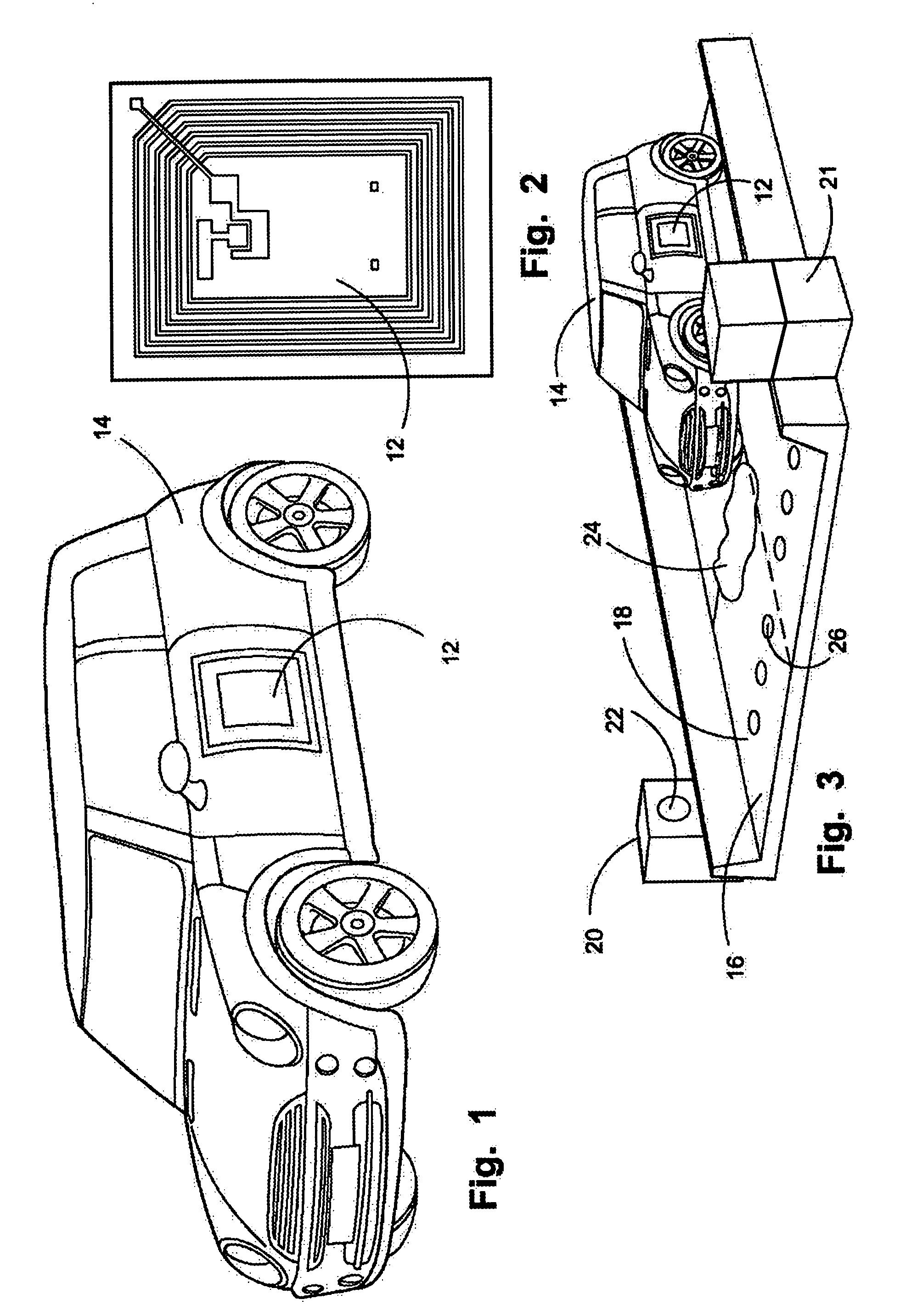
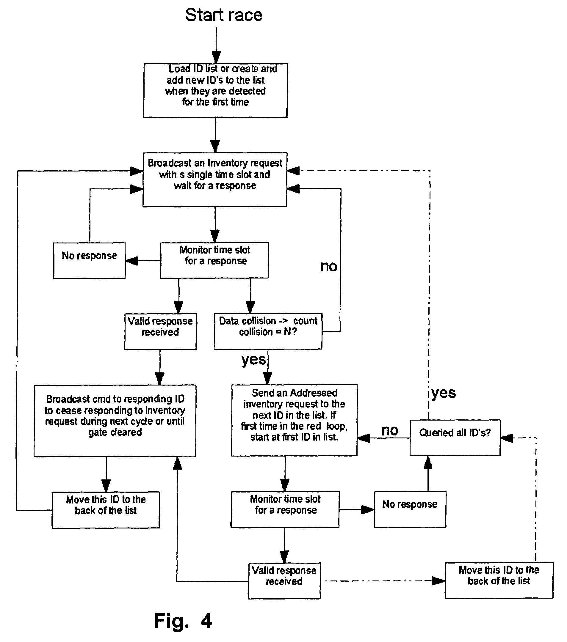
[0046]Referring now to the drawings, FIGS. 1-4 depict the components of the device and system employed for remote control vehicle identification and tracking. These components may also be used in the registration system for race participants on a local or national scale. In addition to tracking the entrants in a race around a single race track, the device and system may also be used to track the individual racers and cars at a plurality of venues having substantially identical tracks. Essentially, using substantially identical or equal distance racetracks located at remote venues, the racers could race against each other and the system would track the progress of the various entrants around the various tracks to determine the winners.

[0047]In use the RFID tag 12 would have an onboard memory capability employing a microchip or other memory storage device which uses either programable memory or read only memory that would be programed with the car's identity along with the owner and a...


PUM


Abstract

An apparatus and method for automatically tracking each individual vehicle, of a plurality of vehicles, in a race around a track. The device employs RFID tags on each of the vehicles being tracked and at gates adapted to cause the RFID to energize and broadcast the vehicle's identity when a pass through the gate is determined. Collisions of data transmission and resulting loss of identification data are reduced through commands to RFIDs responding and remedied with an inventory command based on most likely respondents. The device can be employed to both track the individual vehicle participants in a race and also to register the participants in the race. Races can be tracked on different courses in different geographic locations by placing the RFID tags on all participants and tracking their progress on the individual remote tracks from a central location.

Description

[0001]This application is a Continuation-in-Part Application from U.S. patent application Ser. No. 11,053,311 filed on Feb. 7, 2005 and currently pending which claims benefit to U.S. Provisional 60 / 617,248 filed on Oct. 7, 2004.BACKGROUND OF THE INVENTION[0002]1. Field of the Invention[0003]The present invention relates to vehicle racing. More particularly the device herein disclosed relates to a method and apparatus for the identification and tracking of vehicles used to race upon a defined track.[0004]2. Prior Art[0005]The racing of vehicles has been a popular sport since the dawn of the motor vehicle itself. Such races generally pit a plurality of vehicles against each other to complete a defined distance around a defined track in the fastest amount of time. As a general rule, the distance is a multiple of individual lengths or laps around a track of a determined length.[0006]A vexing problem for such racing which has also been around since racing first began is the tracking of t...

Claims


Application Information

Patent Timeline
Patent Type & Authority Patents(United States)
IPC IPC(8): G08B13/14
CPCA63H18/026G08G1/017A63B71/06G08G1/042
Inventor LE, MICHAEL Q.
Owner LE MICHAEL Q
Learn More