
Shoe apparatus with improved efficiency

a technology of efficiency and shoe, applied in the direction of shoes, top-pieces, heels, etc., can solve the problems of running fatigue or injury, fatigue to the wearer, fatigue to at least, etc., and achieve the effect of reducing the damage of the suspension element by overflexing

Active Publication Date: 2008-02-26
HANN ATHLETIC LLC
View PDF74 Cites 55 Cited by
  • Summary
  • Abstract
  • Description
  • Claims
  • Application Information

AI Technical Summary

Benefits of technology

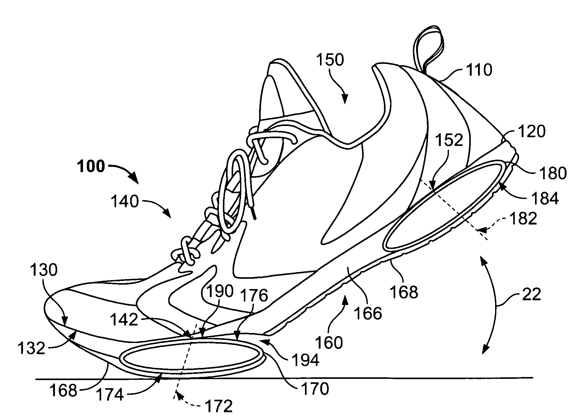
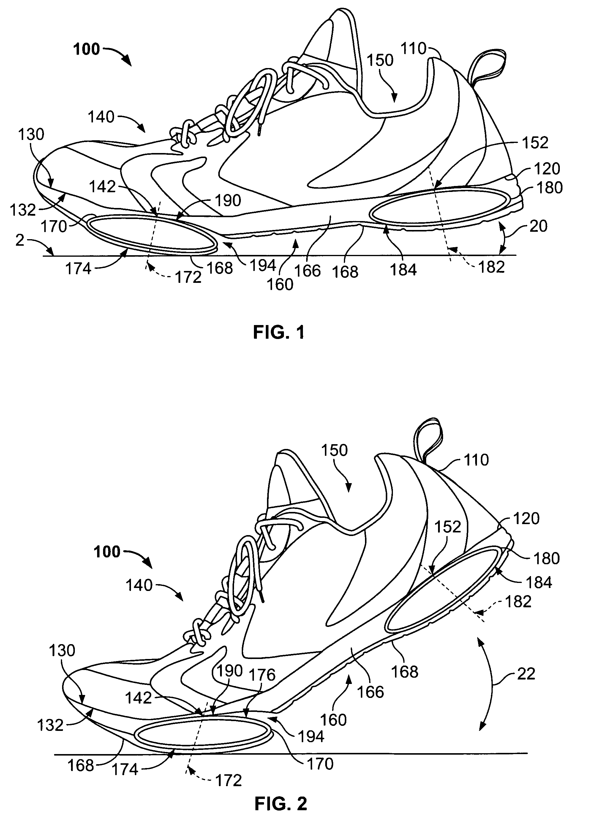
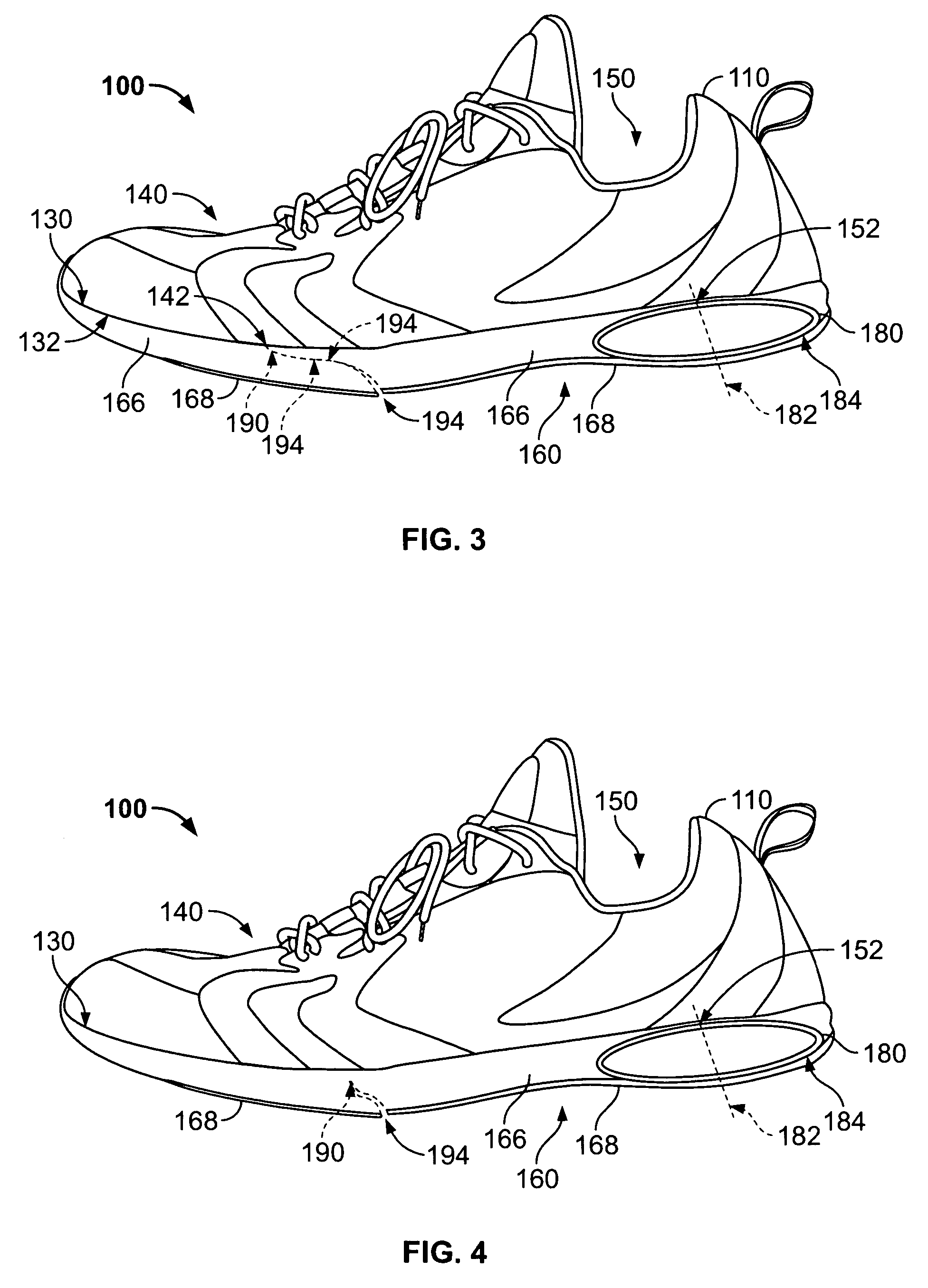
[0033]In another embodiment, the shoe comprises a suspension element having a foam element running from the first lateral side to the second lateral side in the area of the center of compression of the suspension element. The foam element can take the form of an over-travel bumper, which is connected only the lower inner surface of the suspension element, to minimize overflex damage to the suspension element.

Problems solved by technology

Using shoes for walking, running, and other activities for an extended period of time, distance, or both can cause fatigue to the wearer, including fatigue to at least the muscles, tendons, ligaments, and cartilage of at least the feet, legs, and torso.
This fatigue can be caused by several factors, such as the impact forces resulting from the change in the rate of change of loading or “bottoming out” of conventional shoe materials.
Benno M. Nigg, 1997) explains that neither the magnitude nor duration of impact forces experienced during running is the primary cause of running fatigue or injuries.
Muscle tuning is the source of localized neuromuscular fatigue.
The muscle tuning effect is often quite pronounced and leads to cumulative fatigue and diminished endurance.
However, prior shoes do not manage impact forces in such a way as to minimize muscle tuning.
Using midsole material above and below the spring diminishes the effectiveness of the spring.
In addition, limiting the spring element's location to being laterally within the midsole can cause stability problems.
The springs are “wave” springs and are made of a metal material, which can cause the shoe to become heavy and inflexible, thereby reducing the efficiency of the shoe.
This arrangement suffers from at least the deficiencies of Crowley, and additionally may cause unwanted strains on the user's feet, difficulty in manufacture, and a lack of a cohesive (one piece) feel to this shoe in view of the springs not being integral with the sole.

Method used


Image

  • Shoe apparatus with improved efficiency
  • Shoe apparatus with improved efficiency
  • Shoe apparatus with improved efficiency

Examples


Embodiment Construction

[0081]While this invention is susceptible of embodiment in many different forms, there are shown in the drawings and herein described in detail preferred embodiments with the understanding that the present disclosure is to be considered an exemplification of the principles of the invention and is not intended to limit the broad aspect of the invention to the embodiments illustrated.

[0082]The composite suspension elements of the present invention are not “springs” in any simplistic sense. Their function is to guide and decelerate the wearer in a linear fashion, in order to provide a low or zero change in rate of loading throughout the stride, as will be discussed further below. The suspension elements may be a single piece composite or made in two halves, upper and lower, which may provide more linearity and effective suspension travel at a slight increase in element weight. For ride quality and motion control purposes, the suspension elements may feature small cutouts, ridges, profi...


PUM


Abstract

A shoe is provided for improving use efficiency through reduction of neuromuscular fatigue. The shoe includes an upper having a generally horizontal bottom wall. The bottom wall includes an upper surface and a lower surface. The upper comprises a forward region having a forward center of loading and a rear region having a rear center of loading. The shoe further includes a sole comprising a midsole and an outsole. The midsole comprises a suspension element, which can have a generally elongated shape. The suspension element further has a center of compression, which is generally aligned with at least one of the first and second centers of loading of the upper. The shoe can have a hinge located within the sole for providing enhanced efficiency to the user. The hinge and suspension element(s) can take various forms. The position and structure of the hinge and suspension element(s) in relation to the midsole can take various forms as well. The biomechanical action of the heel element, forefoot element and hinge can be dynamically coupled to create a highly resilient suspension system with a low rate of loading throughout the stride, thus allowing a natural, “barefootgait for the wearer. As a result, the wearer experiences a significant reduction in jarring impacts for any phase of the stride, a corresponding reduction in cumulative fatigue and a lower rate of chronic or traumatic injury. A method of manufacturing a suspension element for a shoe is also provided, and includes the steps of providing a die having a length, a width and a thickness, the length accommodating a plurality of suspension elements; wrapping a plurality of coated or wetted fibers around the width of the die to form the suspension elements; drying or curing the fibers to a substantially integrated form; and separating the plurality of suspension elements into independent suspension elements.

Description

TECHNICAL FIELD[0001]The present invention is related to a shoe with improved efficiency in reducing neuromuscular fatigue. More particularly, the present invention relates to an apparatus using a forefoot hinge and / or one or more suspension elements to improve the efficiency of the use of a shoe.BACKGROUND OF THE INVENTION[0002]A traditional shoe has an upper which receives a foot of a wearer, and a sole having a midsole and an outer sole, or outsole, connected to the upper. The upper has a front portion for receiving the toes and front portion of the foot of the wearer, and a rear portion for receiving the rear portion of the foot of the wearer including the heel of the wearer. As the wearer walks or runs, the load of the wearer's body is exerted primarily in two separate locations of each of the wearer's feet. In particular, as the wearer walks or runs, the wearer advances one leg forward along with his / her first foot, and upon contact of the outer sole of the shoe with the groun...

Claims


Application Information

Patent Timeline
Patent Type & Authority Patents(United States)
IPC IPC(8): A43B13/28A43B13/20
CPCA43B13/20A43B13/16A43B13/141A43B13/206A43B13/28
Inventor HANN, LENN
Owner HANN ATHLETIC LLC
Learn More