
DC-DC converter

a converter and dc technology, applied in the direction of electric variable regulation, process and machine control, instruments, etc., can solve problems such as the problem of decreasing efficiency, and achieve the effect of high-efficiency dc-d

Active Publication Date: 2008-02-19
PANASONIC CORP
View PDF12 Cites 38 Cited by
  • Summary
  • Abstract
  • Description
  • Claims
  • Application Information

AI Technical Summary

Problems solved by technology

Use of a high-frequency insulating converter in such a power converter would cause the problem of decreasing efficiency as compared with a non-insulating converter.

Method used


Image

  • DC-DC converter
  • DC-DC converter
  • DC-DC converter

Examples


Embodiment Construction

[0033]Hereinafter, referring to the accompanying drawings, a DC-DC converter according to an embodiment of the present invention and an interconnected inverter using the DC-DC converter will be explained.

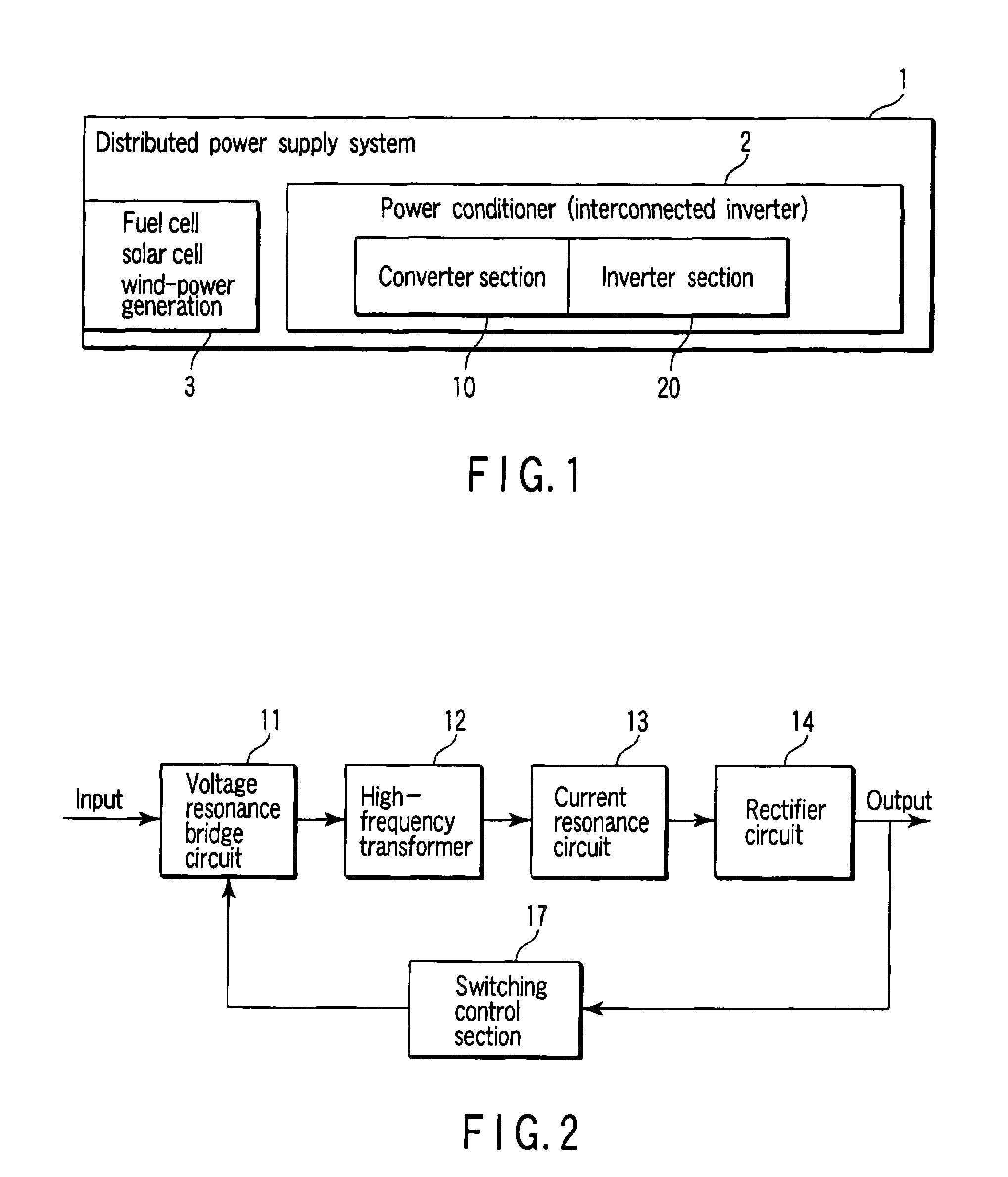
[0034]FIG. 1 schematically shows the configuration of a distributed power system to which an interconnected inverter 2 composed of a converter section 10 (DC-DC converter) according to an embodiment of the present invention and an inverter section 20 that performs DC-AC conversion is applied.

[0035]In the distributed power system of FIG. 1, the output (direct-current electric power) of a direct-current power supply 3 whose output fluctuates, such as a fuel cell, a solar cell, or wind-power generation, is input to an interconnected inverter acting as a power conditioner and then is subjected to DC-DC conversion at the converter section of the interconnected inverter. The converted DC output is converted at the inverter section 20 into a relatively small alternating-current output (e.g...


PUM


Abstract

There is provided a high-efficiency DC-DC converter which comprises a voltage resonance circuit to which electric power from a low-voltage direct-current power supply, including a household fuel cell and a solar cell, is input and performs DC-AC conversion by zero-voltage switching, an insulating high-frequency transformer which transmits the converted power, a current resonance circuit which is provided on the secondary side of the transformer and performs zero-current switching, a rectifier circuit which rectifies the output from the current resonance circuit, and a smoothing circuit which rectifies the output from the rectifier circuit.

Description

CROSS REFERENCE TO RELATED APPLICATIONS[0001]This is a Continuation Application of PCT Application No. PCT / JP2005 / 004824, filed Mar. 17, 2005, which was published under PCT Article 21(2) in Japanese.[0002]This application is based upon and claims the benefit of priority from prior Japanese Patent Applications No. 2004-119652, filed Mar. 18, 2004; and No. 2004-272503, filed Sep. 17, 2004, the entire contents of both of which are incorporated herein by reference.BACKGROUND OF THE INVENTION[0003]1. Field of the Invention[0004]This invention relates to a DC-DC converter. More particularly, this invention relates to an insulating DC-DC converter for a distributed power supply which converts electric power from a distributed direct-current power supply into a medium amount of electric power and an interconnected inverter which uses the DC-DC converter.[0005]2. Description of the Related Art[0006]A distributed power supply system which converts electric power from a distributed direct-curr...

Claims


Application Information

Patent Timeline
Patent Type & Authority Patents(United States)
IPC IPC(8): H02M3/335H02M3/28H02M7/12
CPCH02M3/33523H02M3/3376H02J2001/004H02M2001/0012Y02B10/14H02J3/383H02J3/386Y02E10/563Y02E10/763H02M2001/0077H02J2300/30H02J2300/28H02J2300/24H02J3/381Y02B10/10Y02E10/56Y02E10/76H02M1/0012H02M1/0077H02M7/05
Inventor HORIUCHI, SHOJINAKAMURA, YOSHIMICHITAN, NOZOMI
Owner PANASONIC CORP
Learn More