
Bicycle trainer

a trainer and bicycle technology, applied in the field of bicycle trainers, can solve the problems of difficult to ride trainers, dangerous roller type training devices, and devices without upright restoring for

Inactive Publication Date: 2008-02-05
PETERSON LEWIS DALE +2
View PDF16 Cites 54 Cited by
  • Summary
  • Abstract
  • Description
  • Claims
  • Application Information

AI Technical Summary

Benefits of technology

"The present invention is a bicycle training device that simulates real riding conditions including sprinting and hill climbing. It is supported at the axle mounting of the front forks and at the rear wheel axle, and its real wheel axle is attached to a pivot frame which is centered along the tire contact line. The front mounting forks are attached to the other end of the same pivot frame. The pivot frame is held by a support base and is allowed to tilt angularly in relation to the support base. The angular tilt is controlled by springs and shock absorbers mounted on the base frame and connected to the pivot frame. The force that causes a tilted bicycle to become upright is henceforth described as the righting force. The shock absorbers and springs work together to supply a righting force to the person and bicycle frame through the front and rear axle locations. This angular tilt and righting force provide a real life feel to a bicycle trainer."

Problems solved by technology

This is a problem because these trainers do not permit a person to simulate sprinting and hill climbing by allowing side-to-side pivoting movement of the bicycle as experienced in real riding conditions.
These types of trainers are difficult to ride because there is no upright restoring force and the rider must maintain balance by positioning the bicycle under his or her body in method different from actual riding conditions.
Roller type training devices are also dangerous because they do not secure the bicycle and there is a potential for falling.
However, his device does not have an upright restoring force, but only a side-suspension system that permits a range of lateral movements stretching across the surface of the rollers.
However, this device only allows limited tilting because the upright restoring force is only applied to the rear wheel axle of the bicycle.
The Augspurger device does not offer an upright restoring force through the front forks and this causes frame twisting while only allowing limited angular tilting.

Method used


Image

  • Bicycle trainer
  • Bicycle trainer
  • Bicycle trainer

Examples


Embodiment Construction

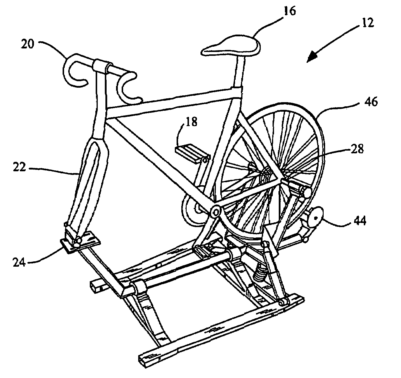
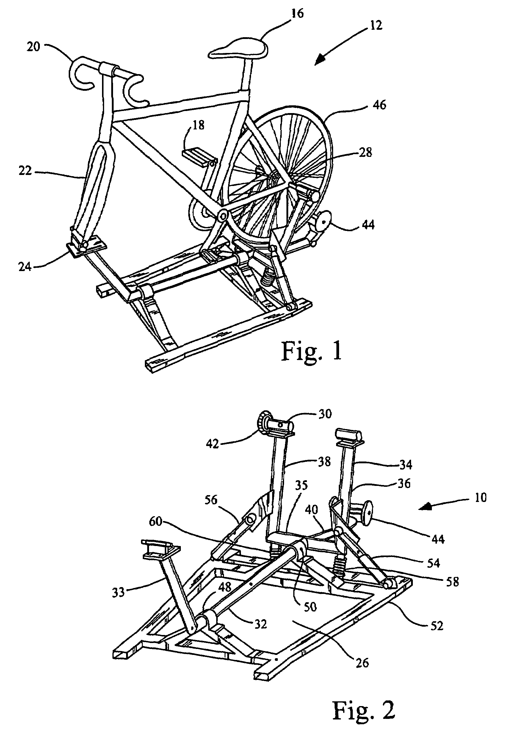
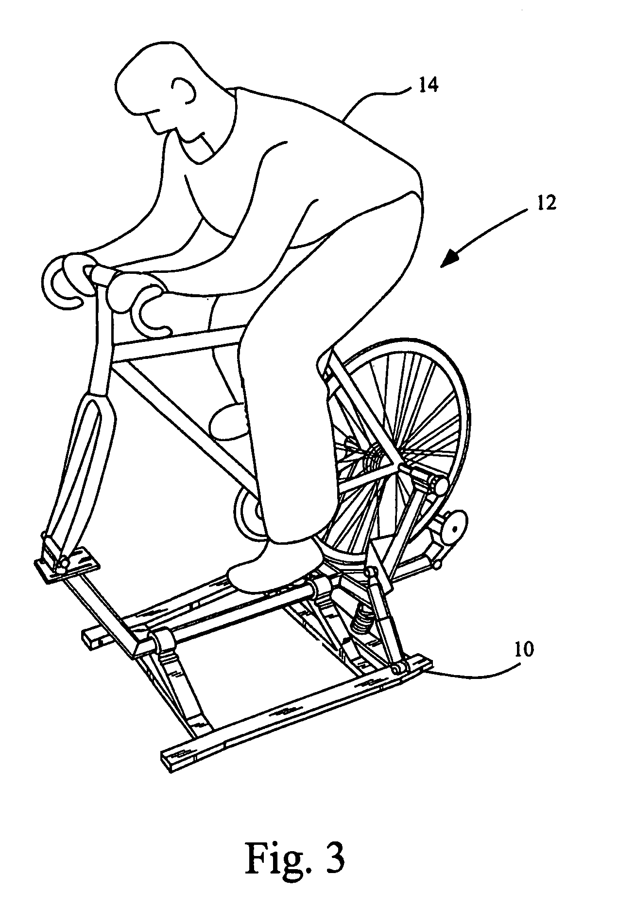
[0019]The present invention referred to hereon as the bicycle trainer 10 can be best understood by a study of FIGS. 1, 2, 3, and 4 along with the following description.

[0020]The bicycle trainer 10 supports a standard bicycle 12, which supports a person 14. The person 14 in a seated position pedaling is supported by seat 16, the pedals 18, and the handlebars 20. The person 14 in a standing position pedaling as shown in FIG. 3 is supported by the pedals 18 and the handlebars 20 with his or her weight shifted upward and forward towards the handlebars 20.

[0021]The bicycle 12 is used in a configuration with the front wheel removed, and the front forks 22 are mounted to the front bicycle mount 24 of the pivot frame 26. The front bicycle mount 24 is a common adjustable fork mount. The front bicycle mount 24 is rigid, but another embodiment allows minimal rotation of the front forks to simulate steering. The rear axle 28 of the bicycle 12 is mounted to the rear bicycle mount 30 of the pivot...


PUM


Abstract

A bicycle trainer adapted to support a conventional bicycle with the front wheel removed. The bicycle is attached to a pivot frame at the front forks and the rear axle. The pivot frame is pivotably attached to the base frame and supported in a substantially upright position by springs. Both the bicycle and pivot frame pivot about an imaginary tire contact-line, which simulates real bicycle riding conditions associated with bicycle sprinting and hill climbing.

Description

CROSS-REFERENCE TO RELATED APPLICATION[0001]Not applicable.STATEMENT REGARDING FEDERALLY SPONSORED RESEARCH OR DEVELOPMENT[0002]Not applicable.REFERENCE TO SEQUENCE LISTING, A TABLE, OR A COMPUTER PROGRAM LISTING COMPACT DISK APPENDIX[0003]Not applicable.BACKGROUND OF THE INVENTION[0004]1. Field of the Invention[0005]This invention relates to exercise equipment and more particularly to an improved bicycle trainer.[0006]2. The Prior Art[0007]Many individuals ride bicycles for training and exercise. However, because of weather and other variables many individuals choose to ride a stationary bicycle trainer as an alternative to riding a bicycle.[0008]Most bicycle trainers on the market have mounted frames and offer no movement of the bicycle other than the pedals and crank. This is a problem because these trainers do not permit a person to simulate sprinting and hill climbing by allowing side-to-side pivoting movement of the bicycle as experienced in real riding conditions.[0009]Other ...

Claims


Application Information

Patent Timeline
Patent Type & Authority Patents(United States)
IPC IPC(8): A63B69/16A63B22/16B62M1/08
CPCA63B22/16A63B69/16A63B2022/0641A63B2069/162A63B2069/165A63B2069/168
Inventor PETERSON, LEWIS DALEMATTHIAS, BENJAMIN JOHNLUCERO, DEWEY ROBERT
Owner PETERSON LEWIS DALE
Learn More