
Electroacoustic transducer

a transducer and electroacoustic technology, applied in the field of earphones or headphones, can solve the problems of increasing the cost of components, increasing the mounting space, and increasing the complexity of the control circui

Inactive Publication Date: 2008-01-29
TOKIN CORP
View PDF22 Cites 33 Cited by
  • Summary
  • Abstract
  • Description
  • Claims
  • Application Information

AI Technical Summary

Benefits of technology

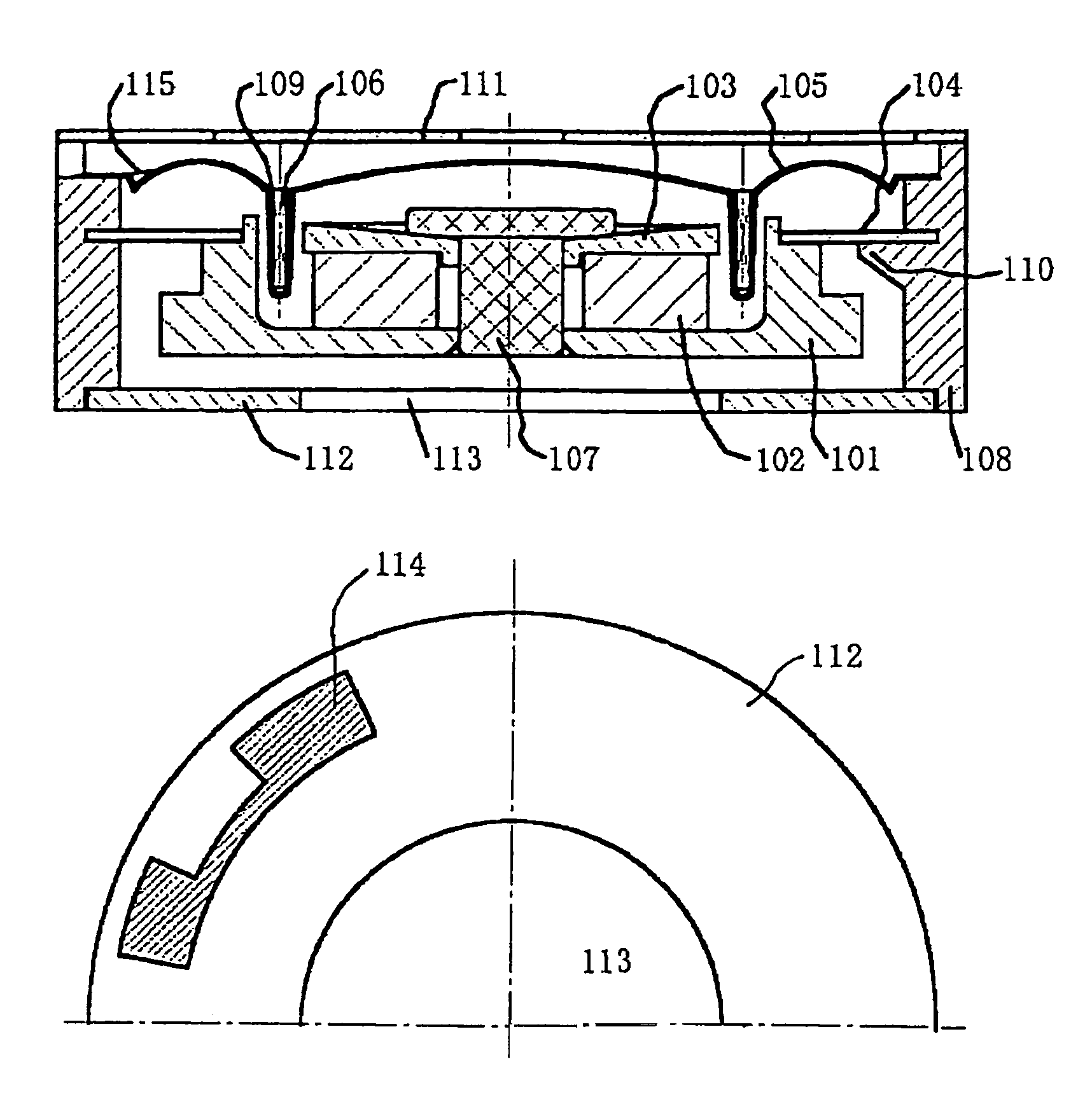
"The present invention is about an earphone or headphone with a vibration actuator that can produce both body-sensitive vibration and sound simultaneously. This allows for the transmission of information through both sound and touch, providing a new way to represent emotions and interact with technology. The vibration actuator uses a magnetic circuit with a permanent magnet, yoke, and plate to concentrate magnetic flux, and a coil placed in an air gap. The actuator is flexible and supported by a suspension formed by a flexible spring. The vibration actuator can vibrate in response to different input signals, resulting in the transmission of vibration to the exterior of the device. This technology provides a new way to experience technology and emote through touch and sound."

Problems solved by technology

Consequently, there have been problems of an increase in cost of the components, an increase in mounting space, complexity of a control circuit, an increase in assembling cost, and so forth.
Further, there has been a problem that, since the sound generating component such as the speaker is small in size and diameter, an output of low-pitched tone is small and therefore a wideband acoustic output cannot be produced.

Method used


Image

  • Electroacoustic transducer
  • Electroacoustic transducer
  • Electroacoustic transducer

Examples


Embodiment Construction

[0024]Hereinbelow, an electroacoustic transducer according to embodiments of the present invention will be described with reference to the drawings.

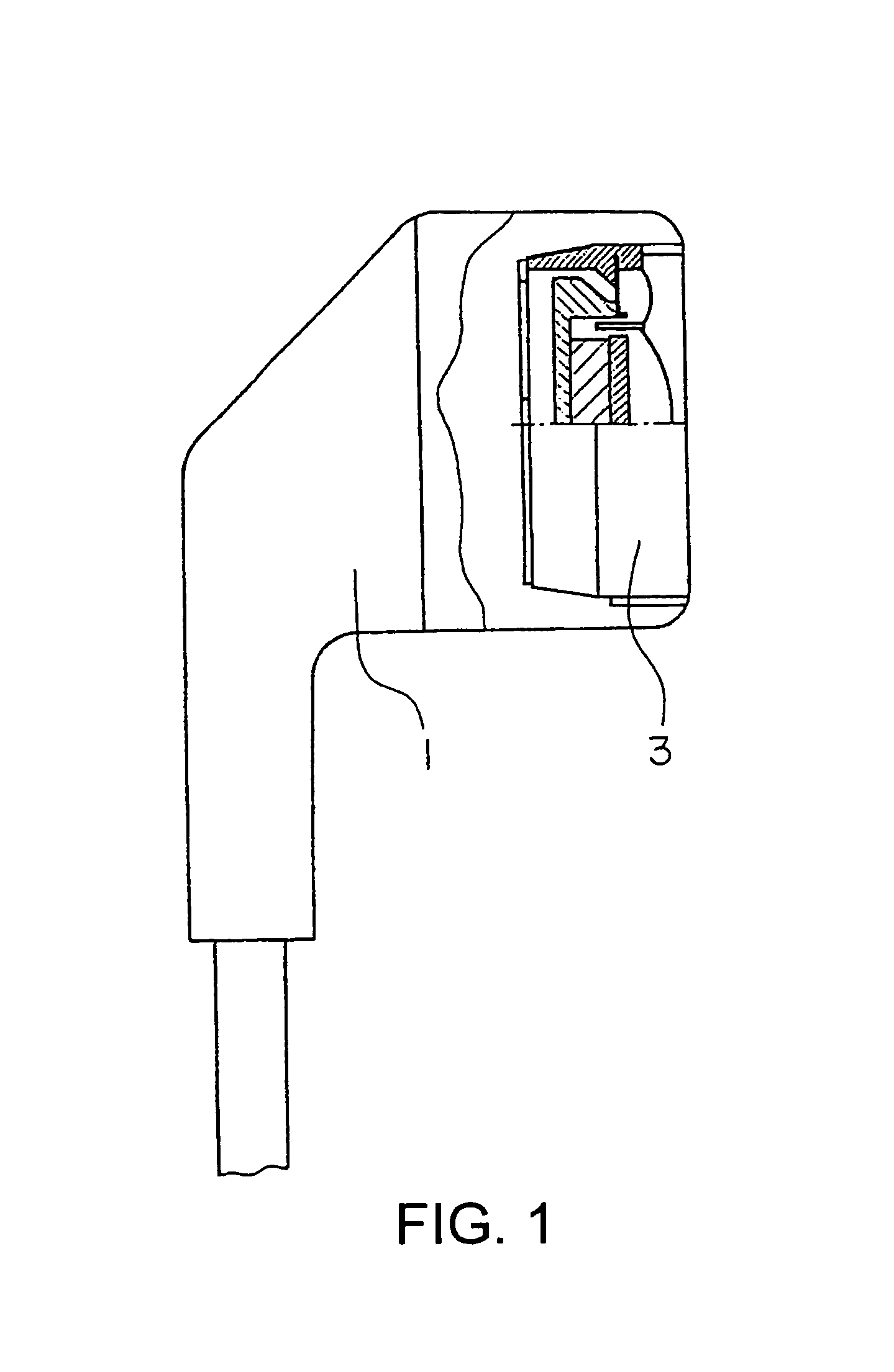
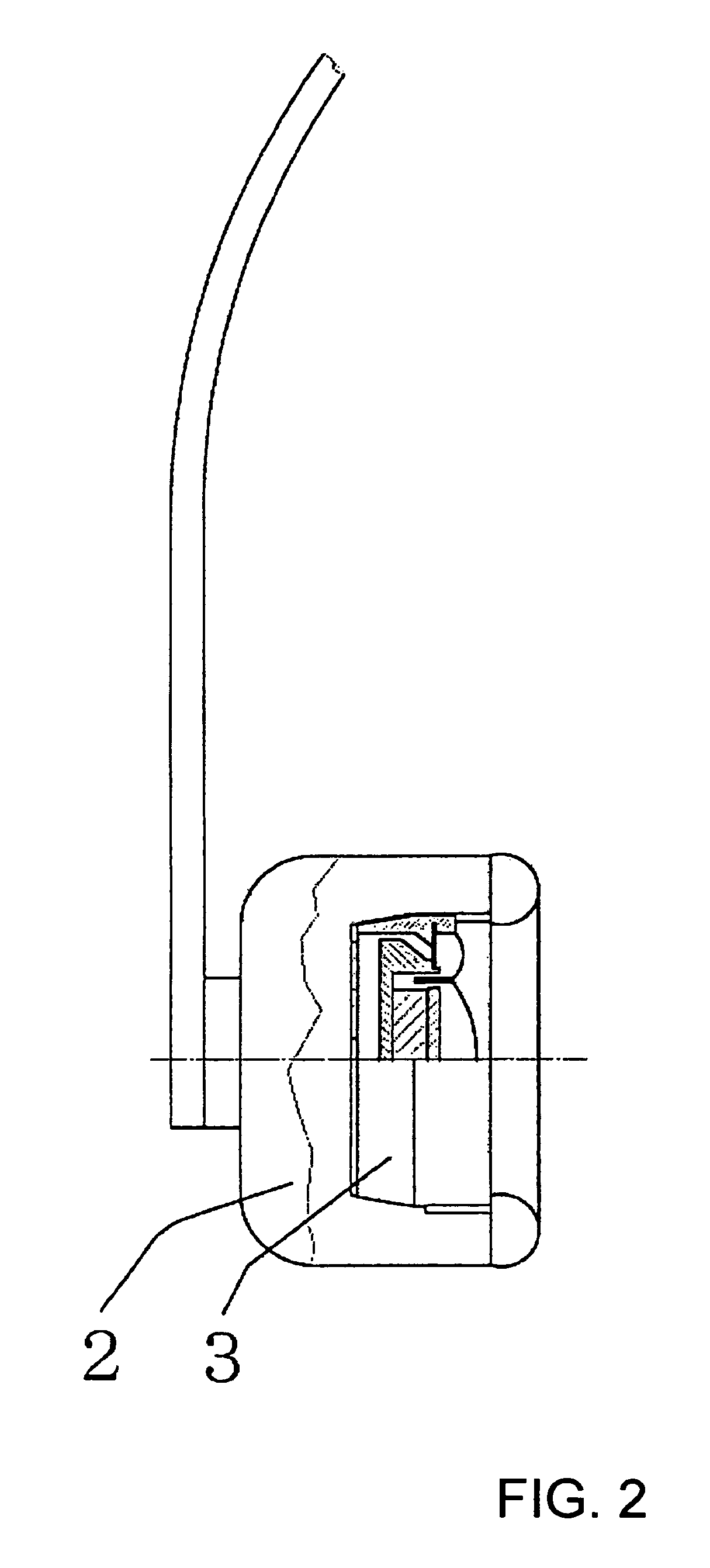
[0025]Referring to FIGS. 1 and 2, outside diameters of vibration actuators 3 mounted in an earphone and a headphone shown in these figures are 13 mm and 17 mm, respectively, and it is therefore possible to realize electroacoustic transducers each having an outside diameter not greater than 20 mm.

[0026]In the vibration actuator 3 used in FIG. 1 or 2, a magnetic circuit has an internal magnet structure in which a disc-shaped permanent magnet 32 is interposed between a yoke 31 and a plate 33, as shown in FIG. 3. A circular magnetic gap G is formed at a portion thereof. A center shaft 37 having a shape of a bolt, a pin, or the like is fitted into a center hole of the magnetic circuit to thereby position the yoke 31, the permanent magnet 32, and the plate 33 on the same axis. A suspension 34 comprises a single piece of an arc-shaped helical l...


PUM


Abstract

A small earphone or headphone which can produce a wide band acoustic output from a low-pitched tone to a high-pitched tone and can generate a body-sensitive vibration independent output or a body-sensitive vibration output synchronized with a music. The earphone or headphone is mounting a vibration actuator which is provided with a magnetic circuit including a permanent magnet, a yoke, and a plate for concentrating the flux of the permanent magnet, with a coil disposed in an air gap of the magnetic circuit, with a diaphragm fixed with the coil and being imparted with a driving force therefrom, and with a vibration transmitting section for supporting the magnetic circuit flexibly through a suspension comprising a flexible spring.

Description

[0001]This application is a U.S. National Phase Application under 35 USC 371 of International Application PCT / JP2003 / 008526 filed Jul. 4, 2003.TECHNICAL FIELD[0002]The present invention relates to an earphone or headphone that is small in size and can produce a body sensible vibration such as a tactile sound, a vibration sound, or a conduction sound (hereinafter a body sensible vibration) and a wideband sound.BACKGROUND ART[0003]FIGS. 4 and 5 are partly-broken side views of a conventional typical earphone and a conventional typical headphone, respectively. As shown in FIG. 4 or 5, the conventional earphone or the conventional headphone of the type incorporates a small-sized speaker 21 with an outside dimension of 13 mm or 30 mm and a height of 2 to 7 mm and thereby has a function of producing a sound. There has also been such an earphone or headphone commercially available that incorporates, separately from the speaker 21, a vibrating member 4 serving as a vibration generation sourc...

Claims


Application Information

Patent Timeline
Patent Type & Authority Patents(United States)
IPC IPC(8): H04R25/00B06B1/04H04R1/10H04R5/033H04R9/10
CPCB06B1/045H04R5/033H04R2400/03
Inventor SATO, MAMORU
Owner TOKIN CORP
Learn More