
Communication system, address management method, relay device, and management device

Inactive Publication Date: 2008-01-29
NTT DOCOMO INC
View PDF5 Cites 3 Cited by
  • Summary
  • Abstract
  • Description
  • Claims
  • Application Information

AI Technical Summary

Benefits of technology

[0010]The present invention has been made in view of the problems stated above, and provides a method and system, in a communication network that mediates packets between mobile terminals, for avoiding a significant increase in traffic, solving the problem of having to provide huge memory capacities, and avoiding packet losses due to changes of packet transfer addresses.

Problems solved by technology

However, in a case where the above addresses are managed by only the NATs disclosed by RFCs 1631 and 2663, the NATs need to translate addresses each time a packet is sent, which imposes a burden on the NATs.
On the other hand, it is difficult for a relay device to assess a memory capacity requirement for storing address binding information of destination terminals of packets, because the number of destination terminals to which packets are addressed is not fixed.
Thus, unless a memory capacity of a relay device is increased sufficiently, the device may run out of memory capacity.
Also, in a case where a relay device inquires address information from a management device each time the relay device receives packets from mobile terminals, there may occur a problem of congestion on a network because of the movement of large numbers of signals from the inquiries.
In a case where a management device continues to store address binding information of mobile terminals which have terminated communication, there occurs another problem that the relay device runs out of memory capacity for storing any subsequent address binding information.
However, if such a request is sent to the management server each time a mobile terminal terminates communication with a communication partner, a problem of congestion on the network because of the movement of large numbers of signals from the requests would occur.

Method used


Image

  • Communication system, address management method, relay device, and management device
  • Communication system, address management method, relay device, and management device
  • Communication system, address management method, relay device, and management device

Examples


modification 1

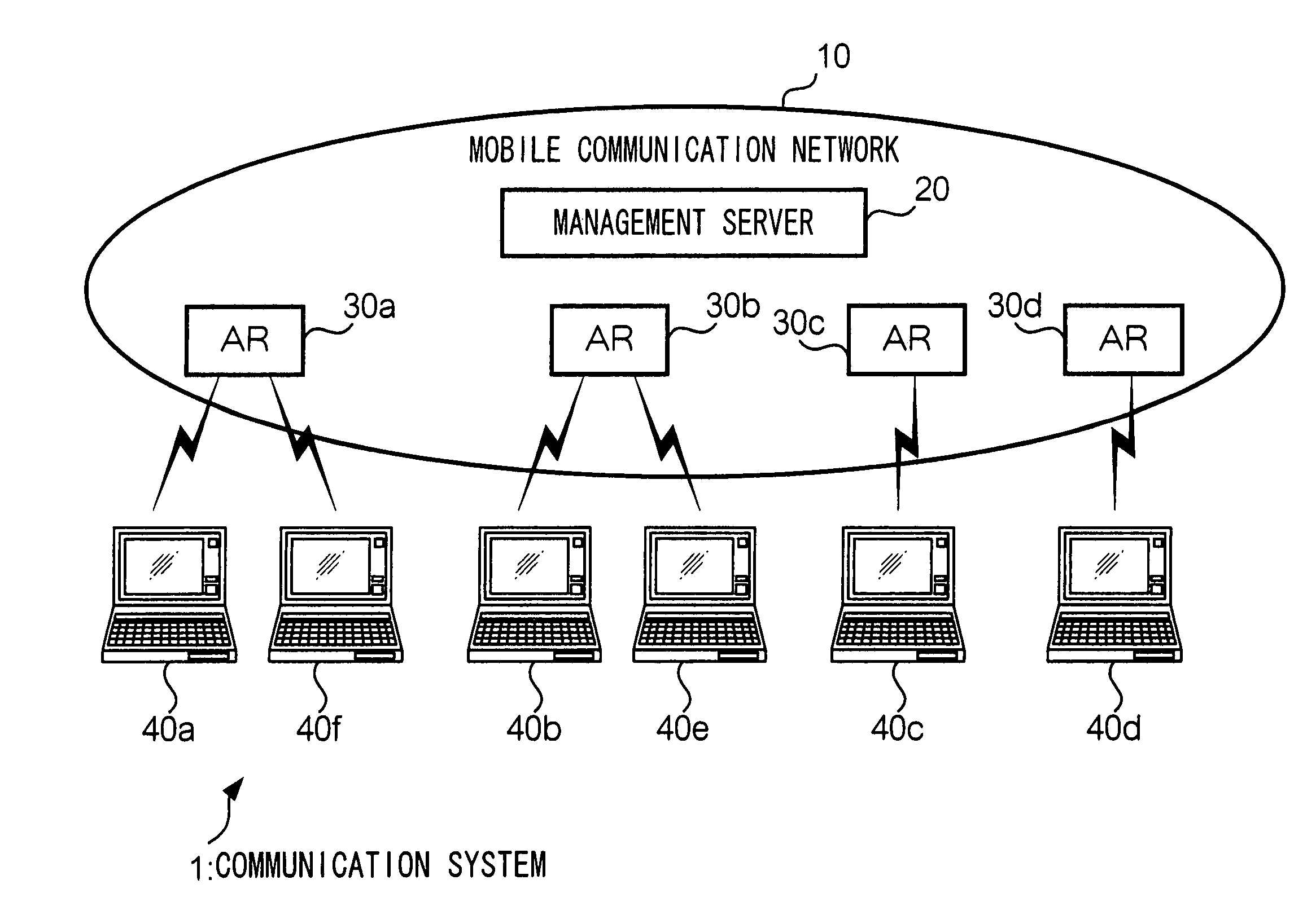
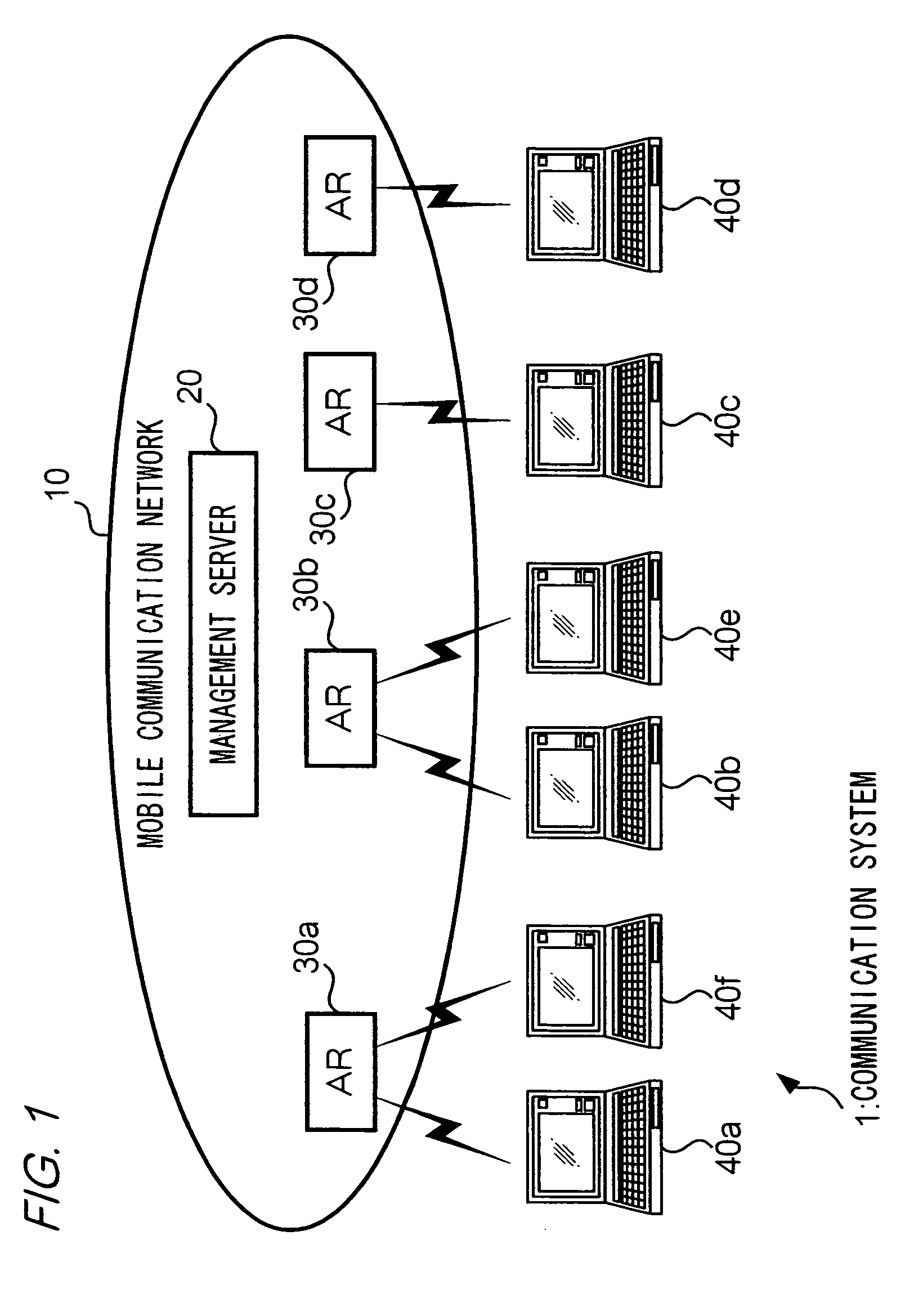
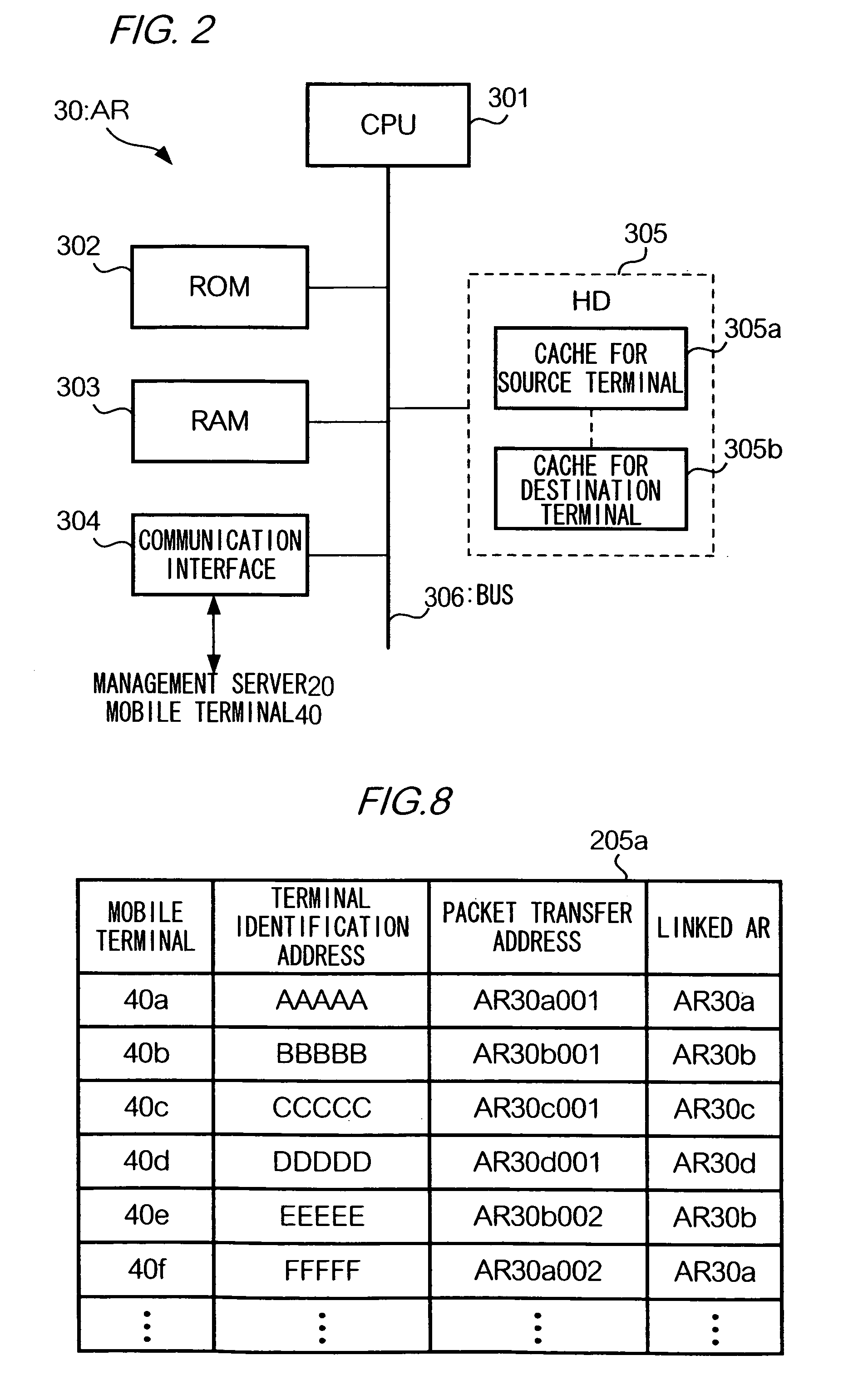
[0114]Mobile communication network 10 may comprise a plurality of routers which have similar functions to AR 30 as described above and are configurable hierarchically or in a multi-layered manner. For example, mobile communication network 10 may further comprise anchor routers (not shown) for transferring packets between a plurality of ARs 30. In the configuration, assigned to each mobile terminal 40 are a first packet transfer address for use between ARs 30 and a second packet transfer address for use between anchor routers. ARs 30 store correspondences between terminal identification addresses and first packet transfer addresses of mobile terminals 40. Anchor routers store correspondences between first packet transfer addresses and second packet transfer addresses of mobile terminals 40. Management server 20 stores correspondences between terminal identification addresses and first packet transfer addresses and second packet transfer addresses of mobile terminals 40. Management se...

modification 2

[0116]In the above embodiment, management server 20, instead of AR 30, may have a function of assigning packet transfer addresses to mobile terminals 40 linked to server 20.

modification 3

[0117]Mobile communication network 10 may further comprise a communication management server (not shown). In a case where the communication management server, instead of management server 20, stores communication chart 205b, the communication management server manages chart 205b in cooperation with server 20.

Configuration 4:

[0118]When messages are exchanged between ARs 30 or between AR 30 and management server 20, a hash function such as MD5, a public key infrastructure, or an Internet key exchange may be used. Thus, the security of communication can be improved between ARs 30 or between AR 30 and management server 20.


PUM


Abstract

A relay device acquires and stores address binding information indicating correspondence between a static communication address and a dynamic communication address of a mobile terminal which is linked to the relay device. The relay device also stores address binding information of other mobile terminals to which packets are sent from the source terminal. A management server stores the address binding information pertaining to the source terminal, and also stores the communication status information of the other mobile terminals with which the terminal is communicating. When the terminal terminates communication, the relay device and the server delete the address binding information pertaining to the source terminal by cooperating with each other.

Description

TECHNICAL FIELD[0001]The present invention relates to a method for managing a static communication address and a dynamic communication address in a communication network that mediates packets by inter-translating the addresses.BACKGROUND ART[0002]There is now in place a technique for transferring packets sent from source terminals to destination terminals by using a static communication address (terminal identification address), which is pre-assigned to a mobile terminal, and by which the terminal can be identified uniquely, and a dynamic communication address (packet transfer address) assigned to the terminal temporarily. As regarding such a technique, RFC 1631 discloses in “The IP Network Translator (NAT)”, a NAT having a function for, when receiving a packet from a mobile terminal, translating into a packet transfer address a terminal identification address designated in a source address of the packet. As a technique derived from the one disclosed by RFC 1631, RFC 2663 discloses ...

Claims


Application Information

Patent Timeline
IPC IPC(8): H04B3/20H04J3/24H04L12/26H04L12/54H04L12/56H04Q7/24H04W40/34H04L12/46H04L45/80H04W8/08H04W8/26H04W28/00H04W60/06H04W80/04H04W88/00H04W88/18
CPCH04L29/12047H04L29/12386H04L29/12471H04L61/15H04L61/2521H04L61/2553H04W8/08H04W8/26H04W60/06H04W80/04H04W88/005H04W88/182H04L61/45
Inventor NISHIDA, KATSUTOSHIOKAGAWA, TAKATOSHIJO, MANHEE
Owner NTT DOCOMO INC
Learn More