
Modular fuel-cell stack assembly

a fuel cell and stack technology, applied in the field of fuel cell stack systems, can solve the problems of adding to the cost of each assembly, complex assembly, and high cost, and achieve the effect of convenient installation and compactness

Inactive Publication Date: 2008-01-29
FUELCELL ENERGY INC
View PDF29 Cites 19 Cited by
  • Summary
  • Abstract
  • Description
  • Claims
  • Application Information

AI Technical Summary

Benefits of technology

This design simplifies and cost-effectively achieves uniform gas flow and pressure distribution, reduces thermal insulation needs, and minimizes piping, resulting in a more efficient and cost-effective modular fuel cell assembly with improved mechanical and thermal performance.

Problems solved by technology

While modular multi-stack fuel cell assemblies of the above type performed as desired, the piping and baffle requirements made each assembly complex and expensive.
The thermal insulation requirements were also stringent, further adding to the cost of each assembly.

Method used


Image

  • Modular fuel-cell stack assembly
  • Modular fuel-cell stack assembly
  • Modular fuel-cell stack assembly

Examples


Embodiment Construction

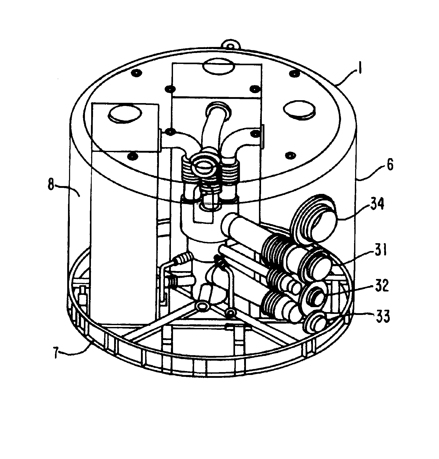
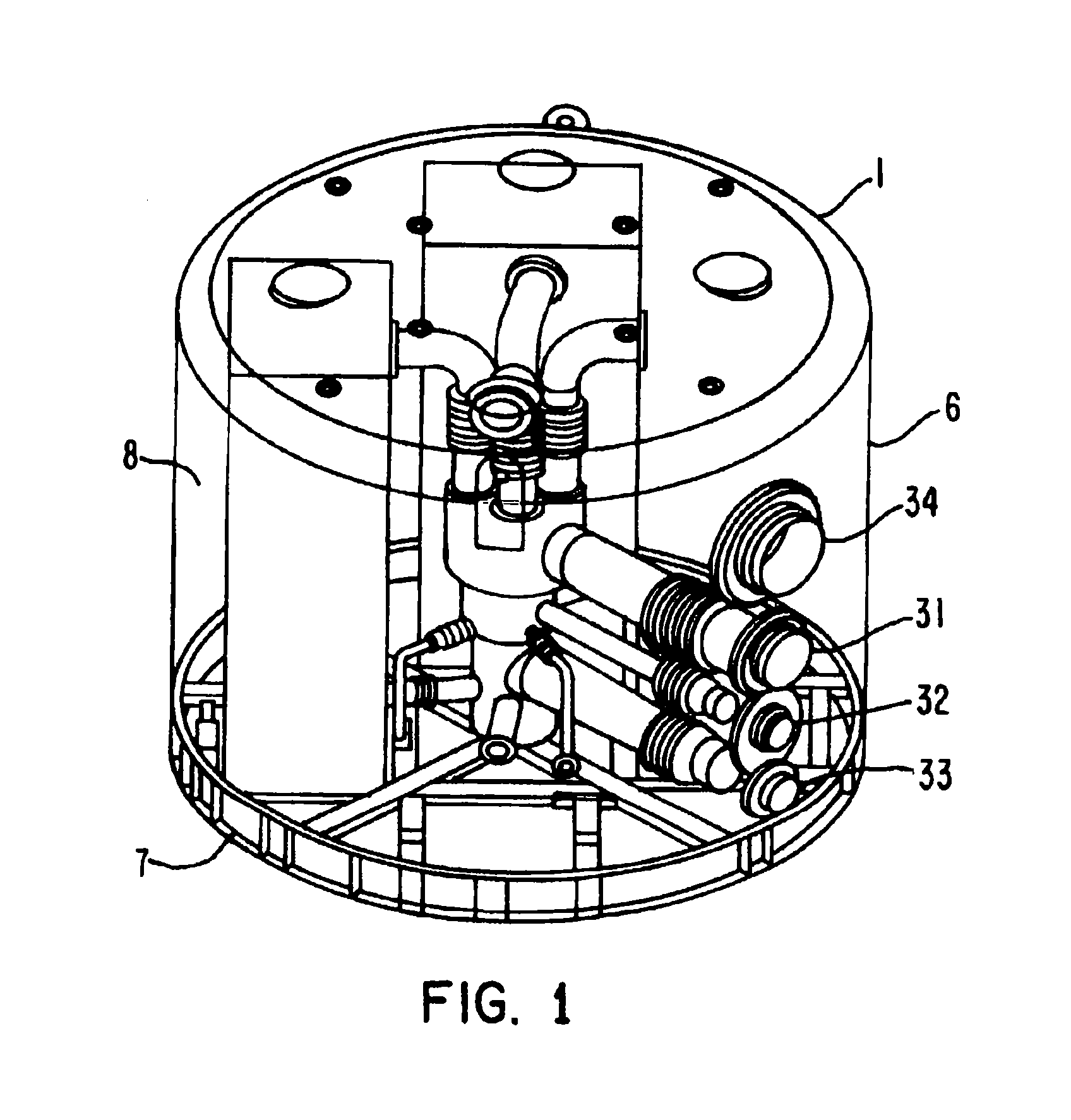
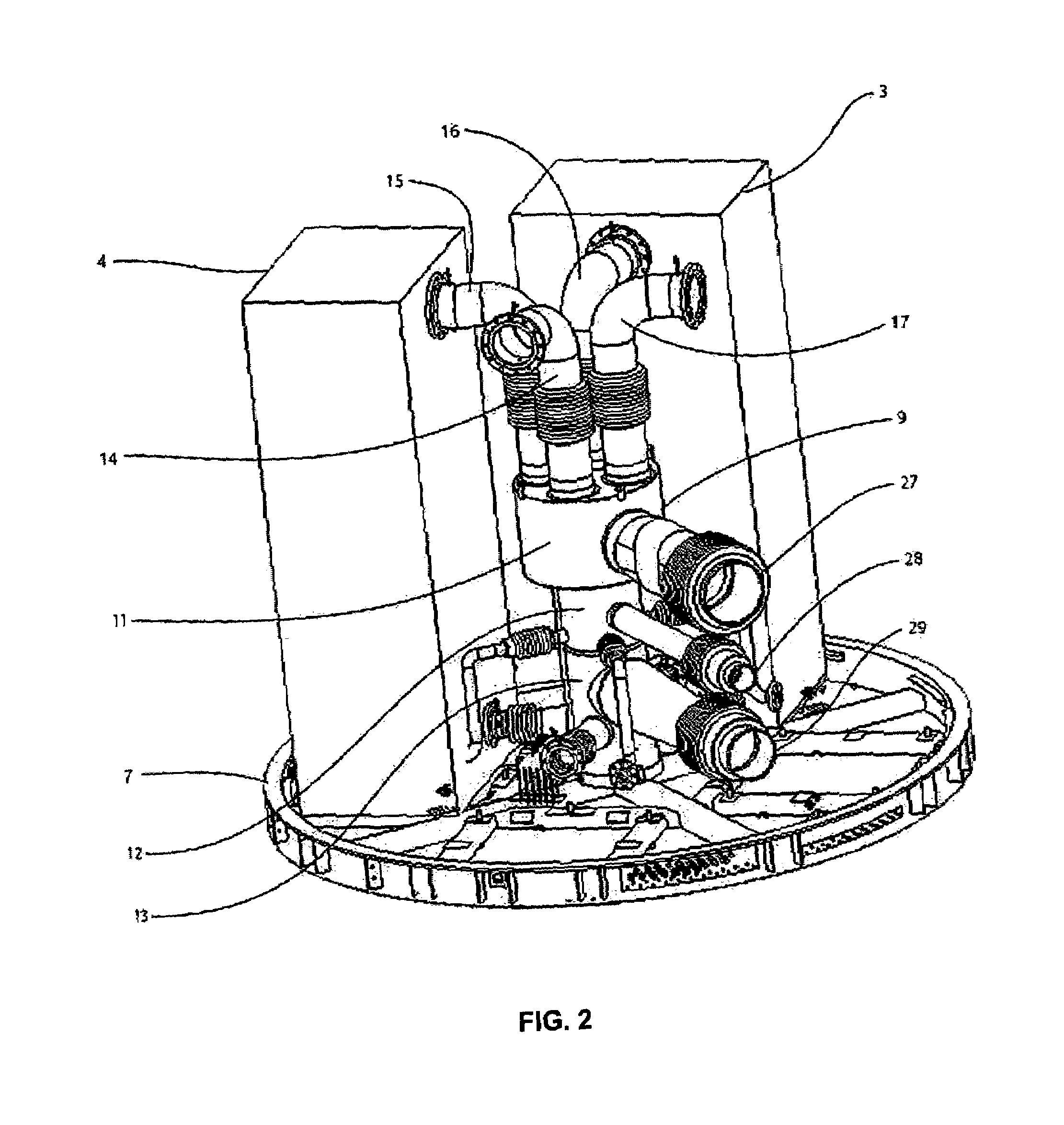
[0034]FIGS. 1-11 show various views of a modular multi-stack fuel cell assembly 1 in accordance with the principles of the present invention. The assembly 1 includes a plurality of like fuel cell stacks, shown as opposing stacks 2 and 3 and opposing stacks 4 and 5. To permit viewing of the other components of the assembly 1, the stacks 2 and 5 are not depicted in FIG. 2, but can be seen FIG. 3 and FIGS. 8-10.

[0035]The stacks 2-5 each extend height-wise in the vertical direction and are supported on a base section 7 of a containment structure 6. The containment structure also includes an upper enclosure 8 (shown in FIG. 1) which surrounds and encloses the fuel cell stacks. Centrally situated relative to the stacks in the enclosure 8 is a gas flow distributor 9 which serves as the unit for the distribution of fuel and oxidant to and from the fuel cell stacks.

[0036]More particularly, referring to FIG. 2, the distributor 9 includes an oxidant exhaust gas section 11, a fuel inlet section...


PUM

PropertyMeasurementUnit
temperaturesaaaaaaaaaa
lengthaaaaaaaaaa

Abstract

A modular multi-stack fuel-cell assembly in which the fuel-cell stacks are situated within a containment structure and in which a gas distributor is provided in the structure and distributes received fuel and oxidant gases to the stacks and receives exhausted fuel and oxidant gas from the stacks so as to realize a desired gas flow distribution and gas pressure differential through the stacks. The gas distributor is centrally and symmetrically arranged relative to the stacks so that it itself promotes realization of the desired gas flow distribution and pressure differential.

Description

STATEMENT AS TO RIGHTS TO INVENTIONS MADE UNDER FEDERALLY SPONSORED RESEARCH AND DEVELOPMENT[0001]This invention was made with Government support under contract DE-FC21-95MC31184 awarded by the Department of Energy. The Government has certain rights in the invention.BACKGROUND OF THE INVENTION[0002]This invention relates to fuel cell systems and, more particularly, to multi-stack fuel cell systems.[0003]In building fuel-cell systems, the fuel cells are conventionally stacked one on the other to form a fuel-cell stack. The number of cells determines the power rating of the stack and to provide systems with higher power ratings, a number of fuel-cell stacks are utilized and the outputs of the fuel cell stacks combined to provide the desired power output.[0004]In one type of multi-stack fuel cell system, it has been proposed to modularize the system by forming modular multi-stack fuel cell assemblies each of which contains a plurality of fuel-cell stacks housed within an enclosure. In ...

Claims


Application Information

Patent Timeline
Patent Type & Authority Patents(United States)
IPC IPC(8): H01M8/02F16L3/00
CPCH01M8/2475H01M8/2485H01M8/249H01M8/04014Y02E60/526H01M2008/147Y02E60/50H01M8/2484H01M8/24H01M8/04
Inventor PATEL, PINAKINURKO, WILLAM
Owner FUELCELL ENERGY INC
Learn More