
Image display device and method

a display device and image technology, applied in the field of image display devices and methods, can solve the problems of slow response speed, lack of imaging repetition stability, and difficulty in maintaining the stability of the dispersion state, and achieve the effect of reducing the drive voltage, reducing the cost and stable construction

Inactive Publication Date: 2008-01-22
BRIDGESTONE CORP
View PDF12 Cites 606 Cited by
  • Summary
  • Abstract
  • Description
  • Claims
  • Application Information

AI Technical Summary

Benefits of technology

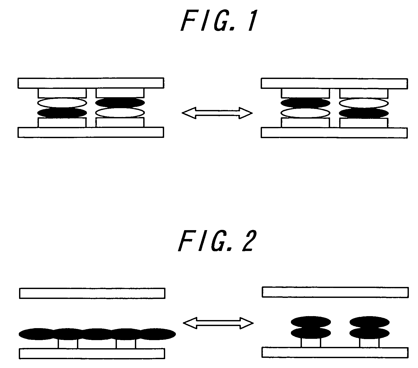
[0007]The first aspect of the invention relates to a new type image display device and method developed for solving the above problems, and has its object to provide an image display device and method which can extremely decrease a drive voltage and have an inexpensive and stable construction in a method of repeatedly displaying the image by utilizing electrostatic.
[0008]The inventors investigated for solving the above problems, and found that it is possible to obtain a new type image display device and method which can realize rapid response and also which can achieve inexpensive and stable construction and further decrease the drive voltage, by utilizing a liquid powder having a fluidity like a solution and an appearance maintaining property like a solid, thereby achieving the present invention.
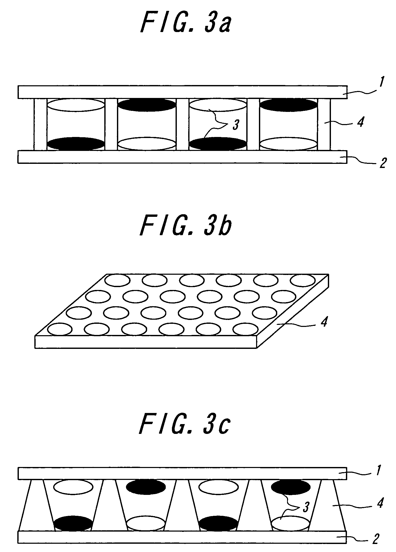
[0029]The second aspect of the invention relates to an image display device developed for solving the above problems, and has its object to provide an image display device which can achieve inexpensive construction, improve durability and decrease a drive voltage, by utilizing a liquid powder having a fluidity like a solution and an appearance maintaining property like a solid.
[0030]The inventors investigated for solving the above problems, and found, in the display device constructed by the opposed substrates and a material movable by Coulomb force, that it is possible to obtain an image display device which can achieve inexpensive construction, improve durability and decrease a drive voltage, by arranging a porous spacer in a space between the substrates in which the liquid powder movable by Coulomb's force is filled, thereby achieving the present invention.

Problems solved by technology

However, in the electrophoresis method, there is a problem that a response speed is slow by the reason of viscosity resistance because the particles migrate among the electrophoresis solution.
Further, there is a problem of lacking imaging repetition stability, because particles with high specific gravity of titanium oxide is scattered within solution of low specific gravity, it is easy to subside, difficult to maintain a stability of dispersion state.
Even in the case of microencapsulating, cell size is diminished to a microcapsule level in order to make it hard to appear, however, an essential problem was not overcome at all.
However, in the above method wherein use is made of a particle behavior in a gas between the substrates, a drive voltage is extremely increased.
Therefore, there arises a drawback such that the particles cannot be moved if the drive voltage is over several hundred volt, while, in the electrophoresis method, the particles can be moved at several dozen volt.
In the dry-type image display device mentioned above, the structure becomes complicated because the charge transport layer and further a charge generation layer are to be arranged on a part of the substrate.
In addition, it is difficult to constantly dissipate charges from the electro-conductive particles, and thus there is a drawback on the lack of stability.

Method used


Image

  • Image display device and method
  • Image display device and method
  • Image display device and method

Examples


example 1

(Production of Liquid Powder)

[0193]Two kinds of the liquid powders (liquid powder X, liquid powder Y) were prepared.

[0194]The liquid powder X was produced as follows. At first, methyl methacrylate monomer, TiO2 (20 phr), charge control agent bontron E89 (Orient Chemical Industries, Ltd.: 5 phr), initiator AIBN (0.5 phr) were suspended and polymerized. After that, particle sizes of the polymerized particles were graded by using a grading device. Then, by using hybridizer (Nara Machinery Co., Ltd.), the polymerized particles, external additive A (silica H2000, Wacker Ltd.) and external additive B (silica SS20, Japan Silica Ltd.) were set therein and treated at 4800 rpm for 5 minuets, so that the external additives were fixed on a surface of the polymerized particles to obtain the liquid powder.

[0195]The liquid powder Y was produced as follows. At first, styrene monomer, azo compounds (5 phr), charge control agent bontron N07 (Orient Chemical Industries, Ltd.: 5 phr), initiator AIBN (0...

example 2

[0205]The display device was produced in the same manner as that of the example 1, except that main materials of the liquid powder X and the liquid powder Y are urethane (in the liquid powder Y, it was used together with carbon).

[0206]The solid state properties of the liquid powder X and the liquid powder Y and the estimation results of the display function in the display device were shown in the following Table 1.

example 3

[0207]The display device was produced in the same manner as that of the example 1, except that an addition amount of the initiator AIBN of the liquid powder X and the liquid powder Y are changed to 0.1 phr.

[0208]The solid state properties of the liquid powder X and the liquid powder Y and the estimation results of the display function in the display device were shown in the following Table 1. In this case, since an addition amount of the initiator AIBN was decreased, the solvent insoluble rate was decreased, and the stability after some time left was slightly deteriorated.


PUM

PropertyMeasurementUnit
particle sizeaaaaaaaaaa
RHaaaaaaaaaa

Abstract

In the image display device according to the first aspect of the invention, a liquid powder composed of a solid material stably floating as a dispersant in a gas and exhibiting a high fluidity in an aerosol state is sealed between opposed substrates, at least one substrate being transparent, and the liquid powder is moved. Moreover, in the image display device according to the second aspect of the invention, a porous spacer is arranged between opposed substrates, at least one substrate being transparent, a liquid powder composed of a solid material stably floating as a dispersant in gas and exhibiting a high fluidity in an aerosol state is sealed, and the liquid powder is moved.

Description

TECHNICAL FIELD[0001]The present invention relates to an image display device and method wherein images can be displayed or eliminated by a movement of particles utilizing electrostatic force.BACKGROUND ART[0002]As an image display device substitutable for liquid crystal display (LCD), image display devices with the use of technology such as an electrophoresis method, an electro-chromic method, a thermal method, dichroic-particles-rotary method are proposed.[0003]As for these image display device, it is conceivable as inexpensive visual display device of the next generation from a merit having wide field of vision close to normal printed matter, having smaller consumption with LCD, spreading out to a display for portable device, and an electronic paper is expected.[0004]Recently, electrophoresis method is proposed that microencapsulate dispersion liquid made up with dispersion particles and coloration solution and dispose the liquid between faced substrates. However, in the electrop...

Claims


Application Information

Patent Timeline
Patent Type & Authority Patents(United States)
IPC IPC(8): G02B26/00G02F1/13G09G3/34G02F1/1671
CPCG02F1/167G02F1/1671G02F1/1679G02F2001/1678
Inventor MASUDA, YOSHITOMOYAKUSHIJI, GAKUMURATA, KAZUYANIHEI, NORIOTAKAGI, KOJITANUMA, ITSUOKITANO, HAJIMEKAWAGOE, TAKAHIRO
Owner BRIDGESTONE CORP
Learn More