
Anti-cogging method and apparatus for a linear motor

a linear motor and anti-cogging technology, applied in electrical equipment, dynamo-electric machines, propulsion systems, etc., can solve the problems of loss of motor efficiency, loss of efficiency, and increased cost of rectangular magnet manufacture, so as to reduce cogging, reduce cogging, and reduce the effect of linear motor cogging

Active Publication Date: 2008-01-08
PARKER INTANGIBLES LLC
View PDF12 Cites 3 Cited by
  • Summary
  • Abstract
  • Description
  • Claims
  • Application Information

AI Technical Summary

Benefits of technology

"The present invention provides a way to reduce cogging in a linear motor. Cogging is a problem that causes efficiency loss and can make motor movement difficult. The invention solves this problem by adding a force that cancels out the cogging force at any motor speed. This force is created by shaped parts attached to the moving part of the motor. The invention also includes sensors and circuitry to detect motor movement. Using this method, cogging can be virtually eliminated with no loss in efficiency."

Problems solved by technology

There is a need to reduce the cogging force because cogging undesirably interferes with the smooth and efficient transfer of power to the motor.
But skewing results in a loss of motor efficiency.
Another prior art method for reducing cogging is to apply shaped magnets, but this too results in loss of efficiency.
Also, the manufacture of shaped magnets is more expensive than the manufacture of rectangular magnets.

Method used


Image

  • Anti-cogging method and apparatus for a linear motor
  • Anti-cogging method and apparatus for a linear motor
  • Anti-cogging method and apparatus for a linear motor

Examples


Embodiment Construction

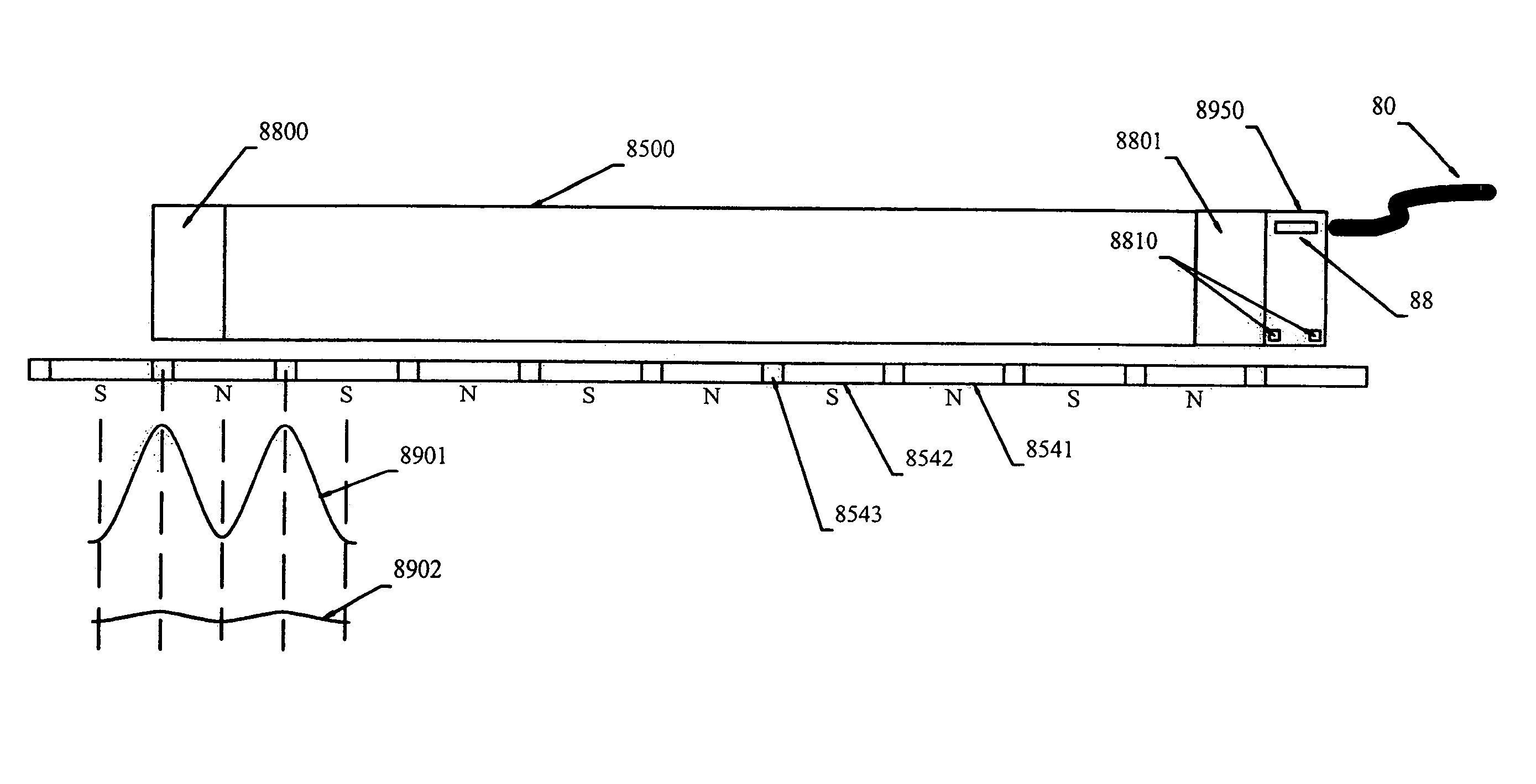
[0021]An embodiment of the present invention is illustrated in the simplified drawing of FIG. 3. A shaped block of permeable material 2060 at an end of motor core assembly 2000 is provided. Also, a shaped block of permeable material 2061 at the opposite end of motor core assembly 2000 is provided. Each shaped block 2060 and 2061 is mounted to move with the motor. As the motor moves along the track of magnets 2540 in track 2200, the vertex 2070 of block 2060 extends into the space above a magnet, and the volume density of permeable material directly above the magnet gradually changes as the motor moves. Similarly, vertex 2071 of block 2061 extends into the space above a magnet, and the volume density of permeable material directly above the magnet gradually changes as the motor moves. As the volume density of permeable material in the space above a magnet gradually increases or decreases, the strength of magnetic coupling between the magnet and the block gradually increases or decrea...


PUM


Abstract

The present invention provides a method for reducing cogging in a linear motor and for mounting sensors to determine motion of the motor.

Description

PRIORITY[0001]This application claims priority of U.S. provisional patent application No. 60 / 554,089 filed Mar. 17, 2004 pursuant to 35 U.S.C. 119(e).TECHNICAL FIELD OF THE INVENTION[0002]The present invention relates to the field of linear motors and methods and apparatus for reduction of cogging.BACKGROUND OF THE INVENTION[0003]Linear motors are used in a variety of applications, including automated positioning systems, robotics, hard drives, semiconductor manufacturing, and electronic assembly. A description of linear motor construction and operation is provided in U.S. Pat. No. 4,839,543, issued to Trilogy Systems Corporation, which is incorporated herein by reference. A position encoder system for positioning linear motors is described in U.S. Pat. No. 6,326,908, also issued to Trilogy Systems Corporation, and also incorporated herein by reference.[0004]Shown in FIG. 1 is an end cross-sectional view, of a conventional assembly for mounting a linear motor. Linear motor coil asse...

Claims


Application Information

Patent Timeline
Patent Type & Authority Patents(United States)
IPC IPC(8): H02K41/00H02K29/06H02K41/03
CPCH02K41/03H02K29/06
Inventor BEAKLEY, BRUCEMARSH, JAMES J.SHAUL, ROBERT T.JUHASZ, BRIAN L.
Owner PARKER INTANGIBLES LLC
Learn More