
Amine recovery apparatus and decarbonation apparatus having same

a technology of amine recovery and decarbonation apparatus, which is applied in the preparation of amino compounds, separation processes, hydrogen sulfides, etc., can solve the problems of reducing the concentration of amine recovered by washing water, sulfur oxide emissions, nitrogen oxides, carbon dioxide, etc., and achieves low operating cost and high ability to recover amine compounds.

Inactive Publication Date: 2008-01-08
MITSUBISHI HEAVY IND ENG LTD
View PDF18 Cites 36 Cited by
  • Summary
  • Abstract
  • Description
  • Claims
  • Application Information

AI Technical Summary

Benefits of technology

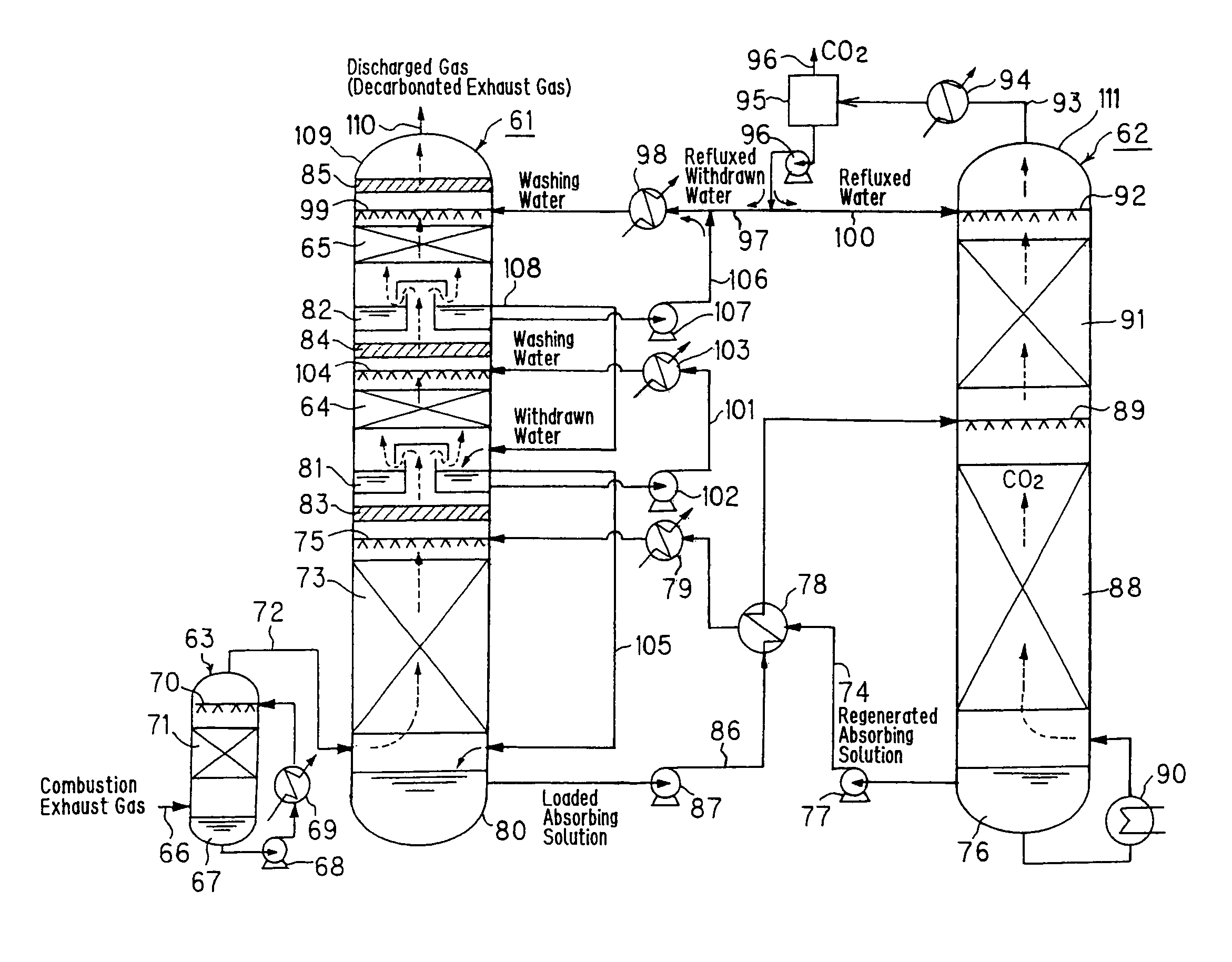
[0017]Thus, according to the amine recovery method as the first invention, the water washing section is constituted in a plurality of stages, and recovery of the amine compound accompanying the decarbonated exhaust gas is performed sequentially in the water washing sections in the plural stages. Consequently, the amine compound accompanying the decarbonated exhaust gas can be recovered very efficiently, and the operating cost can be reduced.
[0043]Thus, the decarbonation apparatus of the ninth invention has the amine recovery apparatus of the fifteenth, sixth, seventh or eighth invention in an absorption tower. Hence, the decarbonation apparatus is an apparatus with a high ability to recover the amine compound and involving a low operating cost.

Problems solved by technology

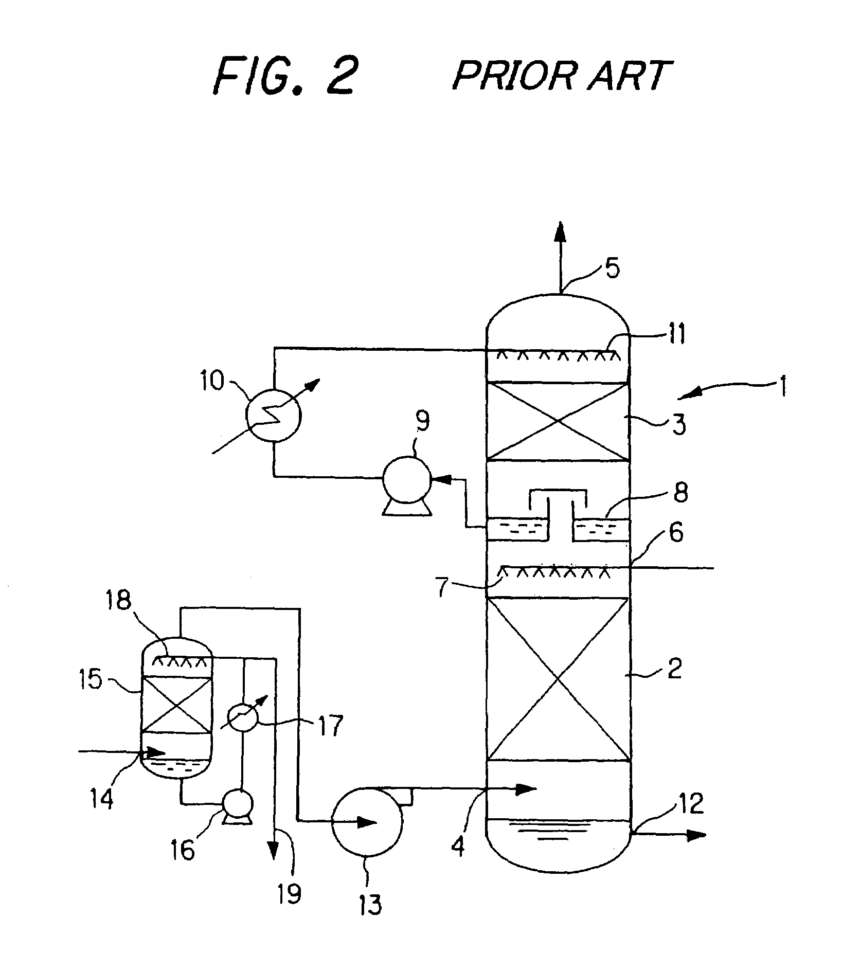
From the points of view of air pollution control and Earth environment purification, it has become problems how to decrease the quantities and concentrations of emissions of sulfur oxides (mainly sulfur dioxide), nitrogen oxides, and carbon dioxide.
Thus, the concentration of amine recovered by the washing water is so high that the recovery of amine is insufficient.
Consequently, amine is wasted, causing a concern about an increase in the operating cost, etc.

Method used


Image

  • Amine recovery apparatus and decarbonation apparatus having same
  • Amine recovery apparatus and decarbonation apparatus having same
  • Amine recovery apparatus and decarbonation apparatus having same

Examples


experiment examples

EXPLANATION FOR CONCRETE EXPERIMENT EXAMPLES

[0079]The present invention will be described concretely by an experimental example, which in no way limit the present invention.

experimental example

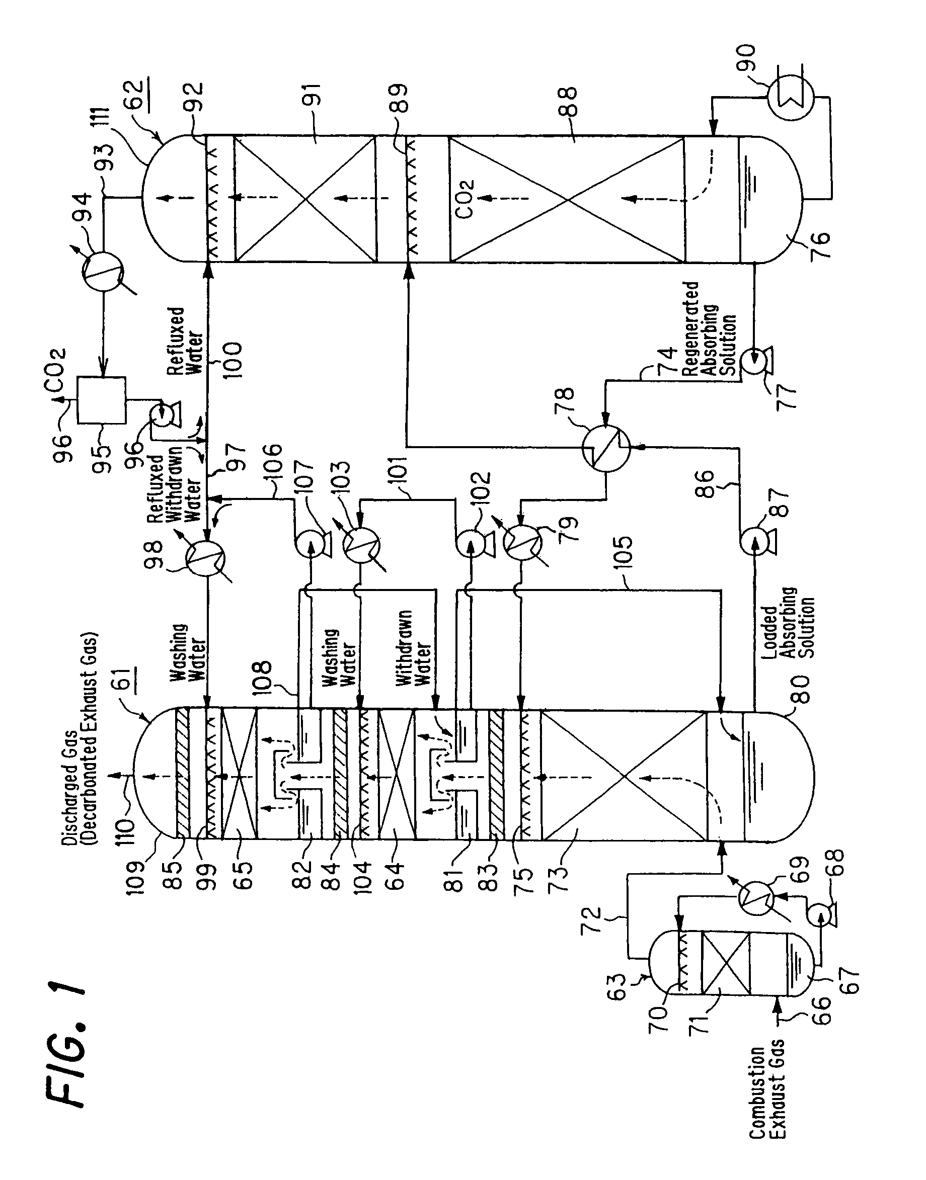
[0080]The following experiments were conducted as the method of the present invention: 30 Nm3 / h of a combustion exhaust gas containing 10% carbon dioxide was supplied to the carbon dioxide absorption section 73 of the absorption tower 61, and brought into countercurrent contact with an aqueous solution of an alcoholic hydroxyl group-containing secondary amine (i.e., an absorbing solution) to absorb carbon dioxide to the aqueous solution. The residual decarbonated exhaust gas was fed to the demister 83 at the outlet of the carbon dioxide absorption section, then brought into countercurrent contact with washing water at a liquid / gas ratio of 2.2 l / Nm3 in the first-stage water washing section 64, and passed through the demister 84 at the outlet of the first-stage water washing section. Further, the decarbonated exhaust gas was brought into countercurrent contact with washing water at a liquid / gas ratio of 2.2 l / Nm3 in the second-stage water washing section 65, passed through the demist...


PUM


Abstract

An amine recovery apparatus includes a carbon dioxide absorption section and plural water washing sections. The carbon dioxide absorption section brings the exhaust gas into vapor-liquid contact with an absorbing solution containing an amine compound and produces decarbonated exhaust gas. The water washing sections bring the decarbonated exhaust gas into vapor-liquid contact with washing water and sequentially recover the amine compound accompanying the decarbonated exhaust gas, while the decarbonated exhaust gas passes through the water washing sections in sequence from inlet portions to outlet portions thereof, respectively. The water washing sections have plural liquid reservoirs provided at the inlet portions of the water washing sections, respectively, and the liquid reservoirs reserve the washing water which is transported to the outlet portions of the water washing sections and supplied to the water washing sections, respectively.

Description

CROSS-REFERENCE TO RELATED APPLICATIONS[0001]This is a divisional application of application Ser. No. 10 / 168,975, filed on Aug. 8, 2002 now U.S. Pat. No. 6,784,320 which is a 371 of PCT / JP01 / 09310, filed Oct. 24, 2001.TECHNICAL FIELD[0002]This invention relates to an amine recovery method and apparatus, and a decarbonation apparatus having the amine recovery apparatus.BACKGROUND ART[0003]In recent years, thermal power equipment and boiler equipment have used large amounts of coal, heavy oil or superheavy oil as fuels. From the points of view of air pollution control and Earth environment purification, it has become problems how to decrease the quantities and concentrations of emissions of sulfur oxides (mainly sulfur dioxide), nitrogen oxides, and carbon dioxide. Suppression of carbon dioxide emission, in particular, has recently been investigated, together with emission control of flon gas and methane gas, from the viewpoint of global warming. For this purpose, methods for removing...

Claims


Application Information

Patent Timeline
IPC IPC(8): B01D53/14B01D53/62B01D53/78B01D53/34C07C211/00
CPCB01D53/1475Y02C10/04Y02C10/06Y02C20/40
Inventor MIMURA, TOMIONOJO, TAKASHIISHIDA, KAZUONAKASHOJI, HIROSHITANAKA, HIROSHIHIRATA, TAKUYA
Owner MITSUBISHI HEAVY IND ENG LTD
Learn More