Variable valve unit for internal combustion engine
a variable valve unit and internal combustion engine technology, applied in the direction of valve details, valve arrangements, valve drives, etc., can solve the problems of assembly error, difficult to adjust the assembly error of the variable valve unit, and assembly error is a factor of generating a difference, etc., to achieve the effect of simple structur
- Summary
- Abstract
- Description
- Claims
- Application Information
AI Technical Summary
Benefits of technology
Problems solved by technology
Method used
Image

Examples
first embodiment
[0039]A variable valve unit according to the present invention will be described below with reference to FIG. 1 to FIG. 9.
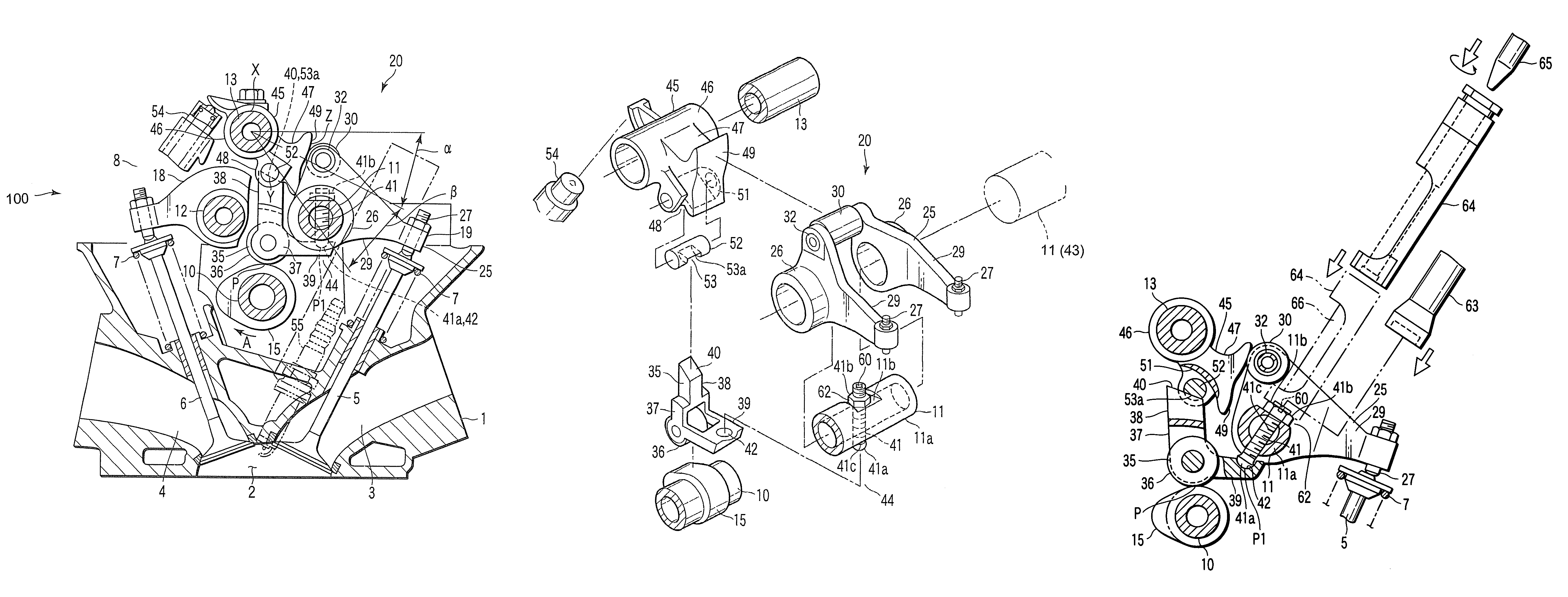
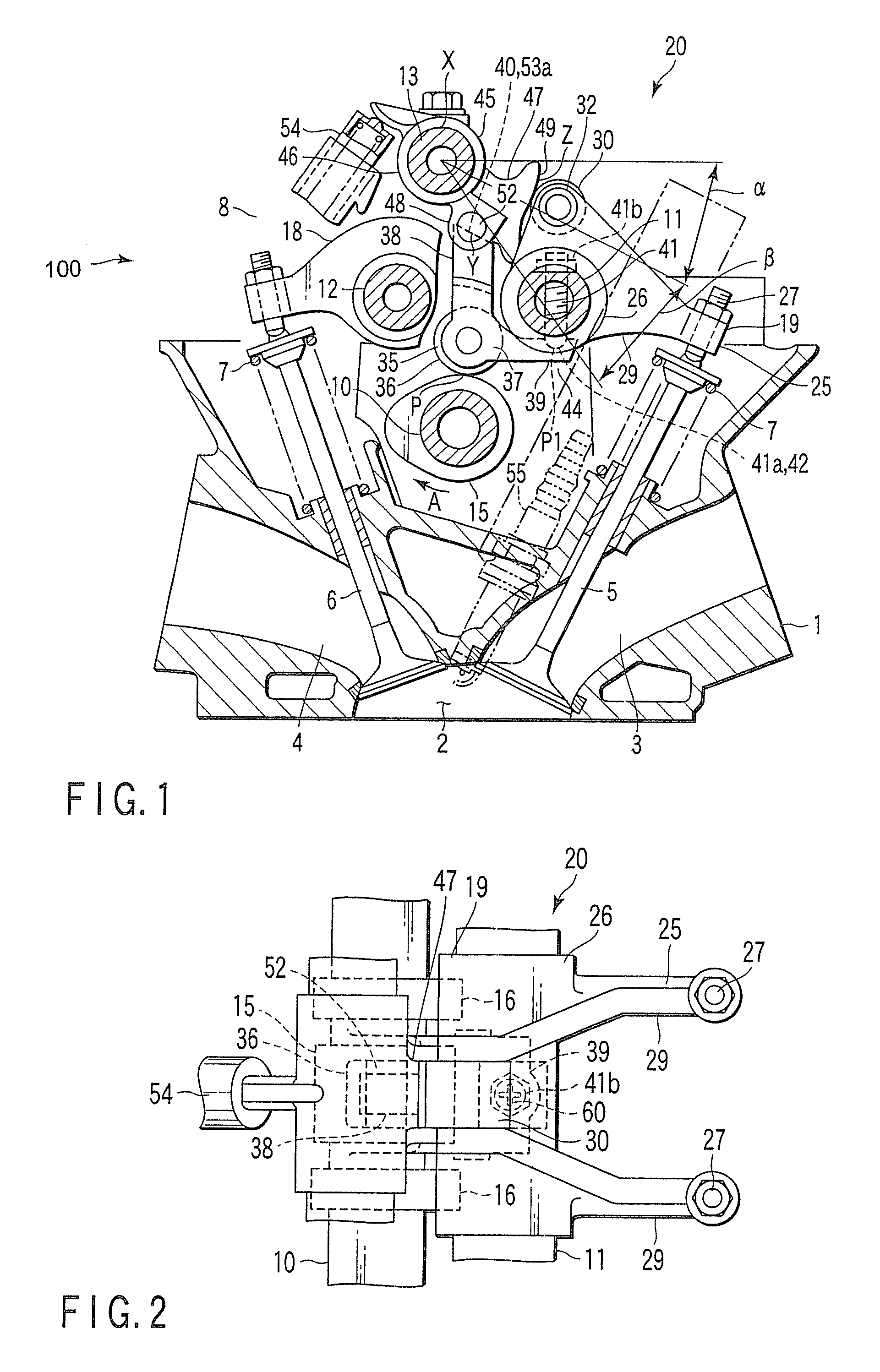
[0040]FIG. 1 is a cross-sectional view showing a cylinder head 1 of a reciprocating gasoline engine 100. The engine 100 includes several cylinders, for example. These cylinders are arranged in series.
[0041]As shown in FIG. 1, the cylinder head 1 is formed with a combustion chamber 2 at the lower portion correspondingly to each cylinder. The cylinder head 1 is provided with a pair of intake ports 3 and exhaust ports 4 for each combustion chamber 2. In FIG. 1, only one side of the intake port 3 and the exhaust port 4 is shown.
[0042]An intake valve 5 is built into the cylinder head 1. The intake valve 5 opens and closes the intake port 3. The intake valve 5 is a reciprocating valve. An exhaust valve 6 is built into the cylinder head 1. The exhaust valve 6 opens and closes the exhaust port 4. The exhaust valve 6 is a reciprocating valve. The foregoing intake and exha...
second embodiment
[0139] an adjustment mechanism 62 is provided in a movable part. Specifically, the adjustment mechanism 62 is provided in the swing cam 45.
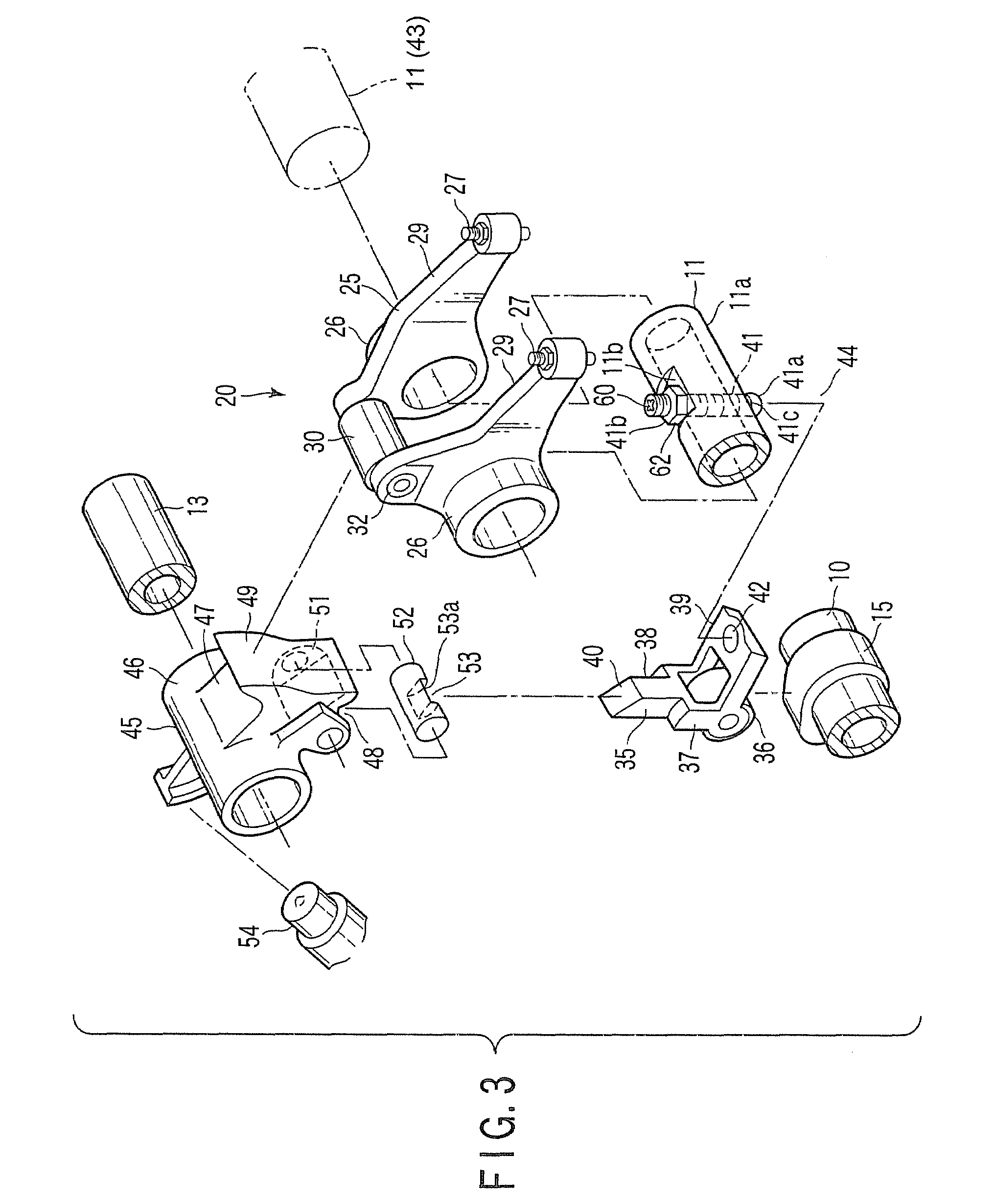
[0140]The adjustment mechanism 62 of the second embodiment will be explained below specifically. As shown in FIG. 11, the tip end portion of the fulcrum arm portion 39 is provided with a lock portion 39a. The lock portion 39a is locked at the lower portion of the outer circumferential portion of the rocker shaft 11. Thus, the center rocker arm 35 is vertically swingable with the lock portion 39a as the fulcrum.
[0141]The pin member 41 extends from the upper side of the arm portion 47 of the swing cam 45 to the lower side. In the arm portion 47, a hole in which the pin member 41 is inserted is formed with an internal thread. Thus, the pin member 41 is screwed into the arm portion 47. In the pin member 41, a portion projecting from the upper portion of the arm portion 47 is clamped with the lock nut 41b. Thus, the pin member 41 is fixed to the arm p...
third embodiment
[0148]The foregoing point will be explained below. In the third embodiment, explanation will be made using the short shaft 52a as one example of the other short shaft.
[0149]As seen from FIG. 12 to FIG. 15, the lower portion of the swing cam 45 is formed with a through hole 51a into which short shaft 52 and the other short shaft different from the short shaft 52 are removably inserted.
[0150]In FIG. 12 and FIG. 13, the short shaft 52a is used. In FIG. 14 and FIG. 15, a short shaft 52a is used. The height dimension of a receiver surface 53a of the short shaft 52 is set to H. The height dimension of a receiver surface 53a of the short shaft 52a is set to H1.
[0151]As illustrated in FIG. 14, the short shaft 52 is replaced with the short shaft 52a, and thereby, a contact state of the inclined plane 40 of the center rocker arm 35 with the receiver surface 53a changes. In FIG. 14, a chain double-dashed line shows the position of the swing cam 45 when the short shaft 52 is used.
[0152]Thus, th...
PUM
 Abstract
Description
Claims
Application Information
 - R&D
- Intellectual Property
- Life Sciences
- Materials
- Tech Scout
- Unparalleled Data Quality
- Higher Quality Content
- 60% Fewer Hallucinations
Browse by: Latest US Patents, China's latest patents, Technical Efficacy Thesaurus, Application Domain, Technology Topic, Popular Technical Reports.
© 2025 PatSnap. All rights reserved.Legal|Privacy policy|Modern Slavery Act Transparency Statement|Sitemap|About US| Contact US: help@patsnap.com