
Node used in photonic network, and photonic network

a photonic network and node technology, applied in the field of photonic networks, can solve the problems of not being able to freely vary the optical path, not being able to make the best possible use of o-lsp resources, and not being able to freely modify the o-lsps according to the needs of the user,

Inactive Publication Date: 2007-12-25
NIPPON TELEGRAPH & TELEPHONE CORP
View PDF23 Cites 16 Cited by
  • Summary
  • Abstract
  • Description
  • Claims
  • Application Information

AI Technical Summary

Benefits of technology

The present invention proposes a multi-layer photonic network, a node, a program, a recording medium, and a path establishment method that can efficiently manage network operations. The invention takes into account path information such as path cost, resource consumption, and traffic quantity to automatically establish paths for optical wavelength links and nodes. The invention also provides a section for automatically establishing a path for an E-LSP based on an establishment request for an E-LSP and the path information of the E-LSP. The invention reduces the burden on the network manager and improves network efficiency.

Problems solved by technology

However, with a conventional multi-layer photonic network, the O-LSPs and the E-LSPs are managed independently, so that it is not possible to modify the O-LSPs freely according to the demand upon the E-LSPs or the traffic fluctuation.
In other words, since each of the O-LSPs operates fixedly via a common carrier leased line or the like, there are the problems that their provision cannot respond to the fluctuations of the packet traffic immediately, and that it is not possible efficiently to make the best possible use of the O-LSP resources.
Furthermore there is the problem that when varying the O-LSP provision, it is necessary to make application to the photonic network administrator, and it is also necessary for the photonic network administrator to change over and establish the O-LSPs manually, and the like.
In addition although it is possible for each node to calculate a path in its own most efficient manner by every node in the photonic network having the same path establishment information, this is troublesome, because it is not necessary to advertise the information regarding a path which is established in order to respond to temporary increase in traffic, to all of the nodes.
However, with a conventional photonic network, the optical paths and the electrical paths are managed independently, and it has not been possible freely to vary the optical paths according to the demand for the electrical paths or the fluctuations of traffic or the like.
Furthermore, since the optical paths have been fixedly established, there have been the problems that it has not been possible to respond to the fluctuations in packet traffic immediately, and that it has not been possible efficiently to make best use of the optical path resources.
Yet further there has been the problem that, when changing an optical path, it is necessary to make application to the photonic network administrator, and for the photonic network administrator to change over the optical path manually, so that the working efficiency has been bad.
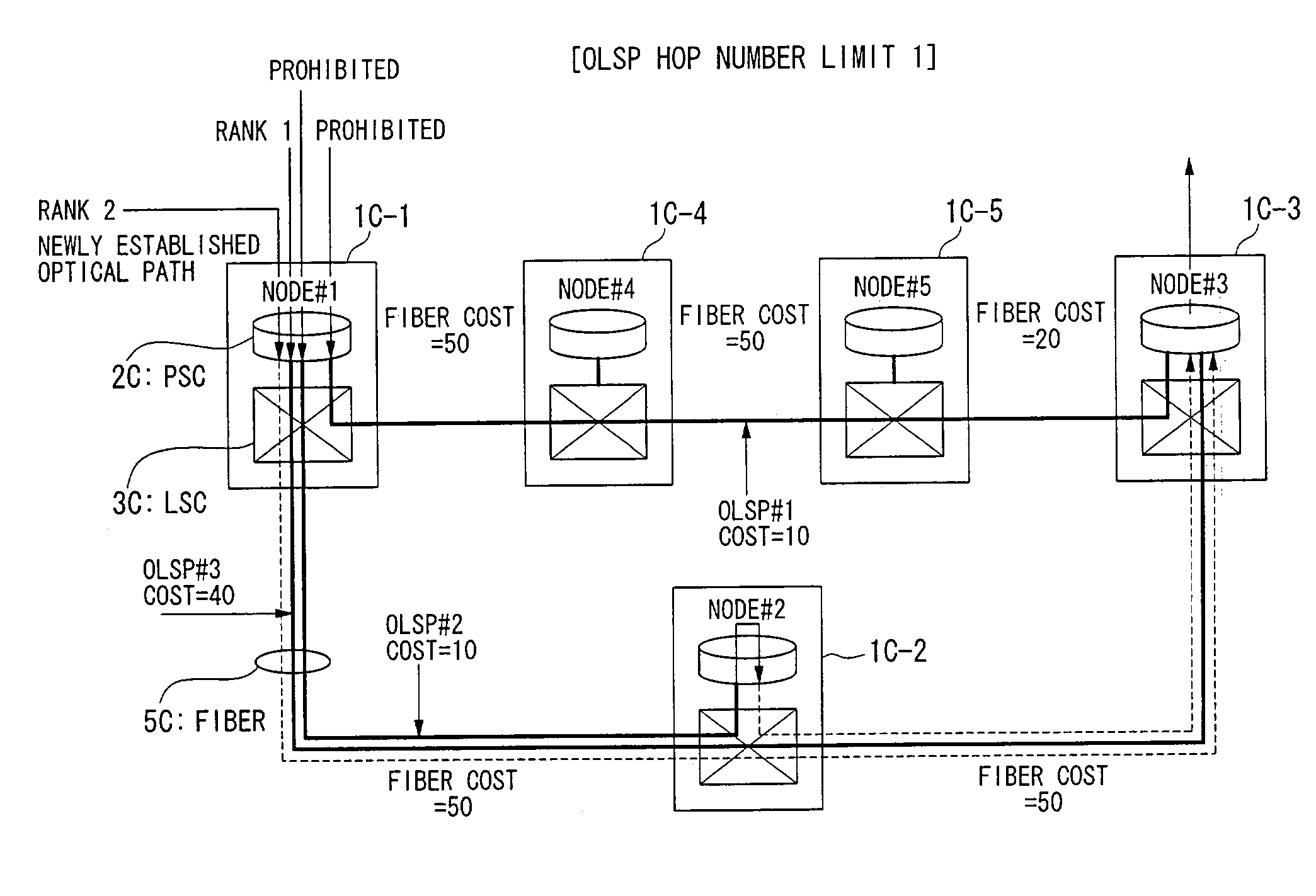
If the optical paths are established without any consideration of the quantity of the traffic, then, for example, it may be the case that no direct optical path is established between some pair of the electrical packet switching sub-networks between which the packet transfer traffic is heavy, and then a necessity may arise for such packet transfer to be performed by multiple hop routing, which may lead to occurrence of the problem of congestion arising upon the optical paths.
However, it is not desirable for the work of maintaining the overall network to be unduly increased, due to the job of establishing the optical paths according to traffic fluctuations in this way being performed manually.

Method used


Image

  • Node used in photonic network, and photonic network
  • Node used in photonic network, and photonic network
  • Node used in photonic network, and photonic network

Examples


Embodiment Construction

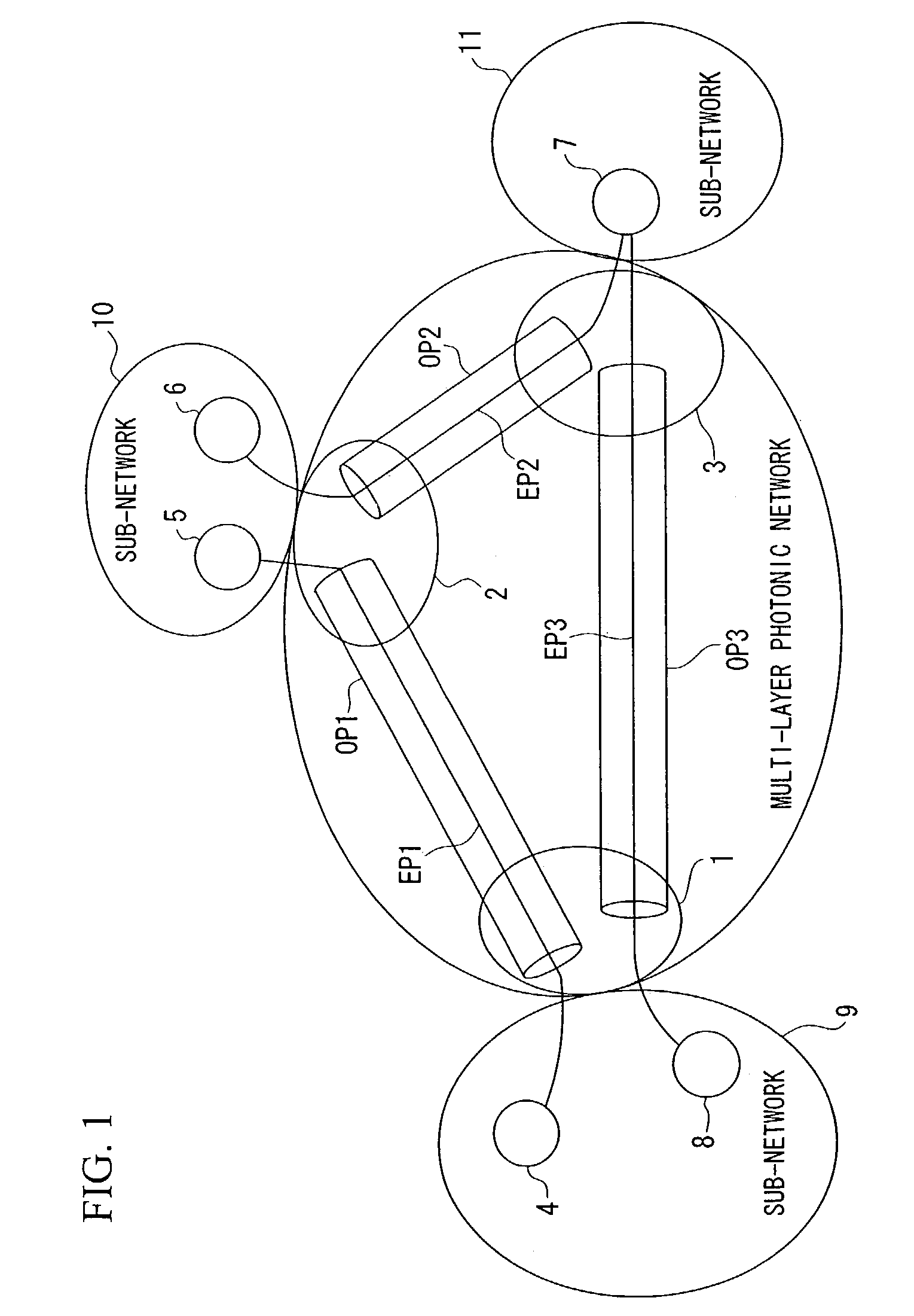
[0275]The first through the fifth preferred embodiments of the multi-layer photonic network according to the present invention will now be explained with reference to FIG. 1. FIG. 1 is a diagram showing the overall structure of the multi-layer photonic network of these first through fifth preferred embodiments.

[0276]As shown in FIG. 1, each of these preferred embodiments is a multi-layer photonic network, comprising a plurality of sub-networks 9 through 11 which perform switching and transfer in packet units, optical paths OP1 through OP3 which are O-LSPs which connect these sub-networks 9 through 1, and nodes 1 through 3 which terminate these optical paths OP1 through OP3; and, in addition to the nodes 1 through 3 which are LSCs which are capable of switching in units of optical wavelengths at both ends of the optical wavelength links which consist of the optical paths OP1 through OP3 and the nodes 1 through 3, there are provided respective border routers 4 through 8 as nodes which...


PUM


Abstract

A multi-layer photonic network and nodes used therein are provided. The multi-layer photonic network comprises a packet network which performs switching and transfer in packet units, and a photonic network comprising optical transmission lines and photonic switches, and which accommodates the packet network. The multi-layer photonic network also has a two layer structure of optical wavelength links (O-LSPs) and packet links (E-LSPs). The O-LSPs are constituted by the optical transmission lines and comprise optical wavelength switching capability (LSC) which is capable of switching in optical wavelength units and packet switching capability (PSC) which is capable of switching in packet units at both their ends. The E-LSPs include the O-LSPs and PSCs at both their ends. Each node includes a section for automatically establishing an O-LSP according to an establishment request for an E-LSP while taking account of path information including path cost, resource consumption, and traffic quantity.

Description

BACKGROUND OF THE INVENTION[0001]1. Field of the Invention[0002]The present invention relates to a photonic network of a multi-layered structure comprising optical paths upon optical wavelengths and electrical paths which use the optical paths.[0003]Furthermore, the present invention relates to a path establishment method in a multi-layer photonic network, which is required for implementing cooperative operation of a high capacity photonic path network which is implemented with photonic cross connect devices, and a service network which is implemented with Layer 2 / 3 switches, which typically are IP routers or the like.[0004]Furthermore, the present invention is applicable to a multi-layer photonic network which is an electrical / optical path integrated communication network. In particular, the present invention concerns the technical field of traffic engineering related to methods and procedures for establishing and releasing optical paths dynamically according to traffic quantities ...

Claims


Application Information

Patent Timeline
Patent Type & Authority Patents(United States)
IPC IPC(8): H04J14/00H04B10/00H04Q11/00
CPCH04Q11/0062H04Q2011/0086H04Q11/0071H04Q11/0066
Inventor OKI, EIJIIMAJUKU, WATARUSHIOMOTO, KOHEIYAMANAKA, NAOAKISHIMAZAKI, DAISAKUNAGATSU, NAOHIDETAKIKAWA, YOSHIHIRO
Owner NIPPON TELEGRAPH & TELEPHONE CORP
Learn More