
Recognition device and method

a recognition device and recognition method technology, applied in the field of recognition devices and methods, can solve the problems of enormous computational quantities required for calculation of the similarity between the input image and the template, the edge is greatly susceptible to lighting conditions, and the amount of template corresponding to the image variation must be prepared, so as to achieve the effect of less learning samples and easy learning

Inactive Publication Date: 2007-12-18
FUJIFILM BUSINESS INNOVATION CORP
View PDF14 Cites 13 Cited by
  • Summary
  • Abstract
  • Description
  • Claims
  • Application Information

AI Technical Summary

Benefits of technology

The present invention is a recognition device and method that can determine if a target is identical to a predetermined reference. It uses multiple deformation units to deform the target with flexibility, and estimates the deformed amount of the target from the reference based on the deformation flexibility. An estimated error evaluation unit evaluates the estimated error of the deformed amount, and an adjustment unit operates the deformation units based on the estimated error. A similarity calculation unit calculates the similarity between the deformed target and the reference, and a judgment unit determines if the target is identical to the reference based on the calculated similarity. This invention allows for realistic image recognition even when the environment of the target changes, and requires less learning samples for learning.

Problems solved by technology

Therefore, an enormous quantity of templates corresponding to image variations must be prepared.
And, a computational quantity required for calculation of the similarity between the input image and the templates also becomes enormous.
As a typical feature point extraction method, a method using an edge operator is known, but a clear edge may not be obtained when a substance has a smooth surface shape such as a face, and an edge is greatly susceptible to lighting conditions.
Therefore, it is necessary to learn all angles to a learning sample, and there are disadvantages that it is necessary to prepare a lot of learning samples and learning takes a long time.
Besides, the above treatise covers rotation in only an image surface as flexibility of deformation of an input image, but an actual image has a high degree of flexibility in a rotation in a depth direction, a size, a position, lighting and the like, resulting in a more serious problem.
Accordingly, it is impossible to complete learning in a realistic time.

Method used


Image

  • Recognition device and method
  • Recognition device and method
  • Recognition device and method

Examples


embodiment 1

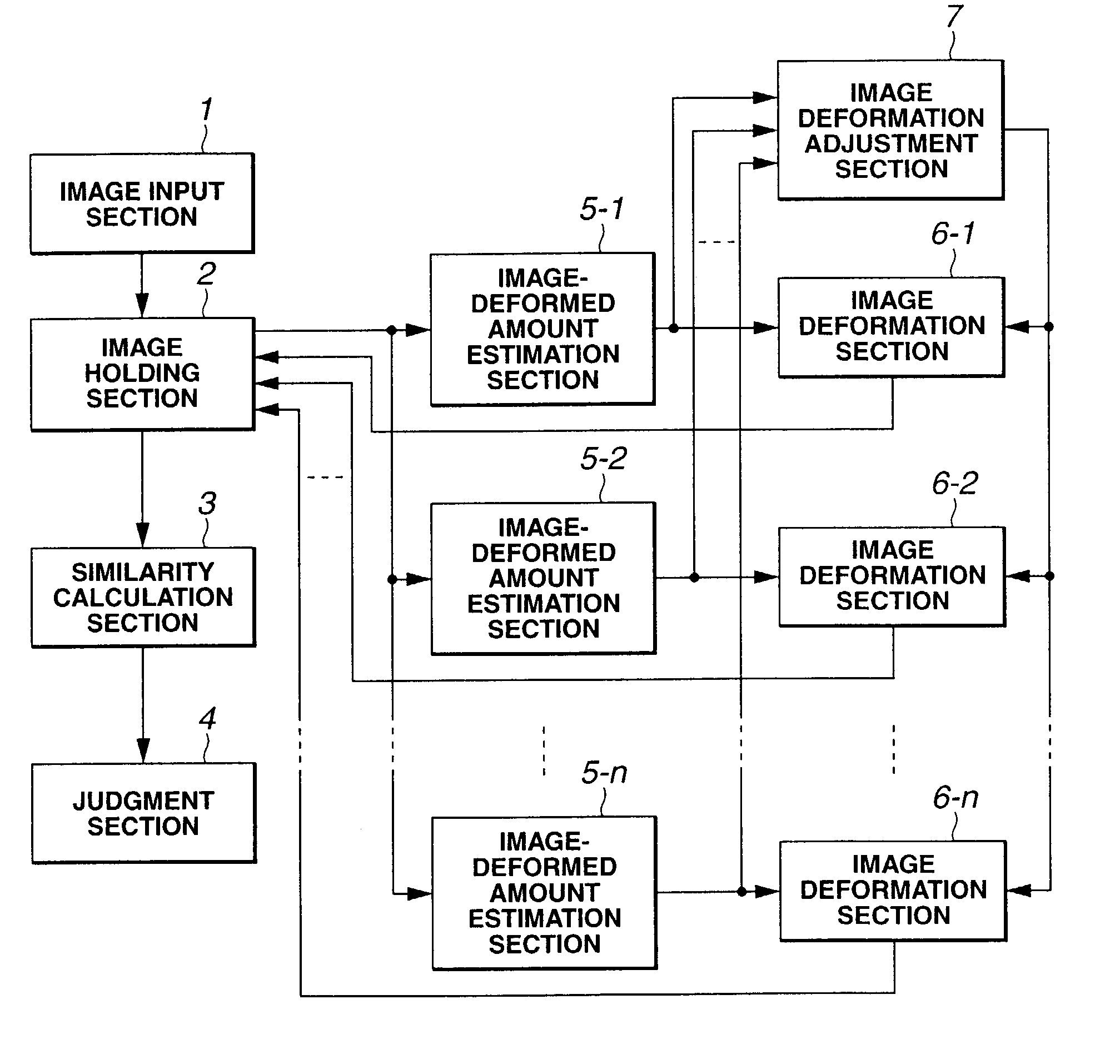
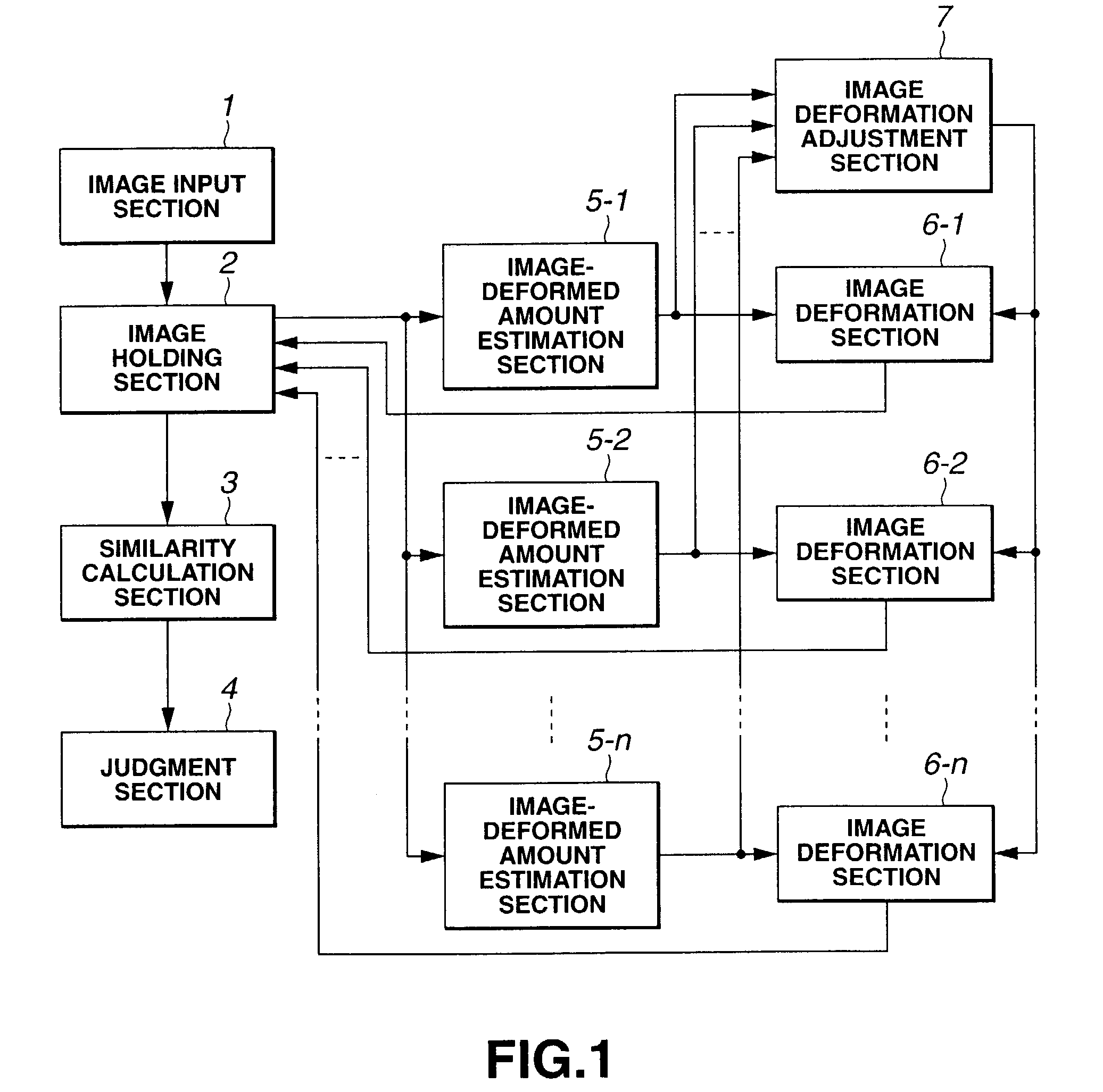
[0031]FIG. 1 is a block diagram showing a functional structure of a recognition device to which the present invention is applied.

[0032]As shown in FIG. 1, the recognition device comprises an image input section 1, an image holding section 2, a similarity calculation section 3, a judgment section 4, multiple image-deformed amount estimation sections 5 (5-1 to 5-n), multiple image deformation sections 6 (6-1 to 6-n) and an image deformation adjustment section 7.

[0033]The image input section 1 inputs an image to be recognized and comprises, for example, a CCD camera.

[0034]The image holding section 2 holds the target image to be recognized input by the image input section 1. The image is held as a vector pattern which, for example, has luminance of each pixel of the image as a component and a dimension of the number of pixels. The held image is deformed appropriately by the image deformation section 6, and the deformed image is held again by the image holding section 2.

[0035]The similar...

embodiment 2

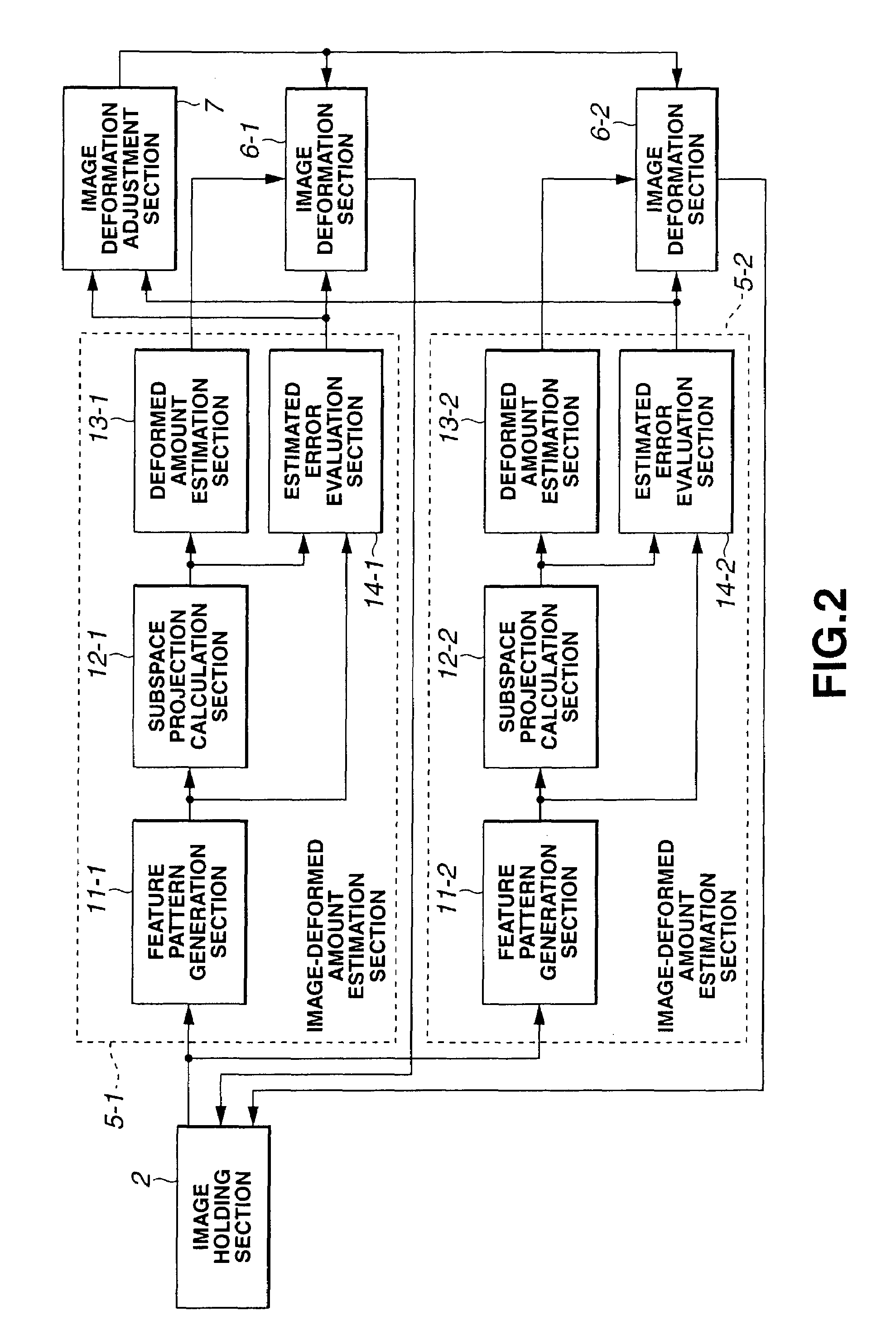
[0072]The recognition device of Embodiment 2 has the same structure as that in Embodiment 1 shown in FIG. 1, and only the processing by the subspace projection calculation section 12, the deformed amount estimation section 13 and the estimated error evaluation section 14 is different. Therefore, only the processing made by the subspace projection calculation section 12, the deformed amount estimation section 13 and the estimated error evaluation section 14 will be described, and other structures will not be described here.

[0073]The subspace projection calculation section 12 has learned the subspace which approximates the distribution of the feature pattern of the reference image. Because a change in the feature vector in a real world is very complex, a nonlinear subspace is preferable to approximate the change. But, instead of learning the nonlinear subspace in the space indicating the feature pattern, Embodiment 2 maps the feature pattern in a higher dimensional space than in the f...

embodiment 3

[0091]In Embodiment 3, a particular voice, for example, “a” is recognized instead of an image. The recognition device of Embodiment 3 has the same structure as that of Embodiment 1 shown in FIG. 1 except that the “image” is replaced by “voice”.

[0092]Therefore, the structure of Embodiment 3 will not be described here. Because differences from Embodiment 1 are an input pattern expression method and an input pattern deformation method, they will be described with reference to FIG. 14. Input voices are sampled at prescribed time intervals and held as a discrete expression with time and two frequency expressions which are Fourier-transformed in a time region designated by a Fourier window. Embodiment 3 has two pattern deformation sections and their corresponding patterns deformed amount estimation sections for the held input. The first pattern deformation section changes the frequency expression to shift the frequency. Meanwhile, the second pattern deformation section changes the time ex...


PUM


Abstract

A recognition device which judges whether a target is identical with a predetermined reference, comprising: a holding unit which holds the target; multiple deformation units which deform the target held by the holding unit with at least one degree of flexibility in deformation; multiple deformed amount estimation units which correspond to the deformation units in a one-to-one relationship and estimate a deformed amount of the target from the reference with respect to the flexibility in deformation according to the corresponding deformation unit; an estimated error evaluation unit which evaluates an estimated error of the deformed amount estimated by the deformed amount estimation unit; an adjustment unit which operates any of the deformation units with precedence according to the estimated error evaluated by the estimated error evaluation unit; a similarity calculation unit which calculates a similarity between the reference and the target which is deformed by the deformation unit operated with precedence by the adjustment unit; and a judgment unit which judges whether the target is identical with the reference according to the similarity calculated by the similarity calculation unit.

Description

BACKGROUND OF THE INVENTION[0001]1. Field of the Invention[0002]The present invention relates to a recognition device and method, and more particularly a recognition device and method which performs a computation on a target such as an image or voice to recognize whether it matches a predetermined reference.[0003]2. Description of the Related Art[0004]For recognition of a recognition target such as a substance or the face of a person with reference to its image, it can be recognized in principle by calculating a similarity of the input image of a substance with a template image of a previously stored reference.[0005]But, the image of an actual recognition target is largely variable depending on environmental conditions such as a direction of the placed recognition target, a distance and lighting. Therefore, an enormous quantity of templates corresponding to image variations must be prepared. And, a computational quantity required for calculation of the similarity between the input i...

Claims


Application Information

Patent Timeline
Patent Type & Authority Patents(United States)
IPC IPC(8): G06K9/68G06K9/00G06K9/48G10L15/20G06K9/64G06T7/00G10L15/16G10L21/02
CPCG10L17/20G06K9/6206G06V10/754
Inventor KATO, NORIJIKASHIMURA, HIROTSUGUIKEDA, HITOSHI
Owner FUJIFILM BUSINESS INNOVATION CORP
Learn More