Flexible tibial sheath

a tibial sheath and flexible technology, applied in the field of tibial sheaths, can solve problems such as torn or ruptured tibias, and achieve the effect of low elasticity

Active Publication Date: 2007-12-18
DEPUY SYNTHES PROD INC
View PDF15 Cites 275 Cited by
  • Summary
  • Abstract
  • Description
  • Claims
  • Application Information

AI Technical Summary

Benefits of technology

[0007]The radially expandable sheath can have a variety of configurations. In one embodiment, the distal portion of the radially expandable sheath, extending between a distal end of the longitudinally oriented slots and a distal end of the sheath, tapers to form a bullet-shaped distal tip. In another embodiment, at least two adjacent sidewalls are joined at a proximal end thereof by a stop member adapted to prevent over-insertion of the radially expandable shea...

Problems solved by technology

In many cases, ligaments are torn or rup...

Method used


Image

  • Flexible tibial sheath
  • Flexible tibial sheath
  • Flexible tibial sheath

Examples


Embodiment Construction

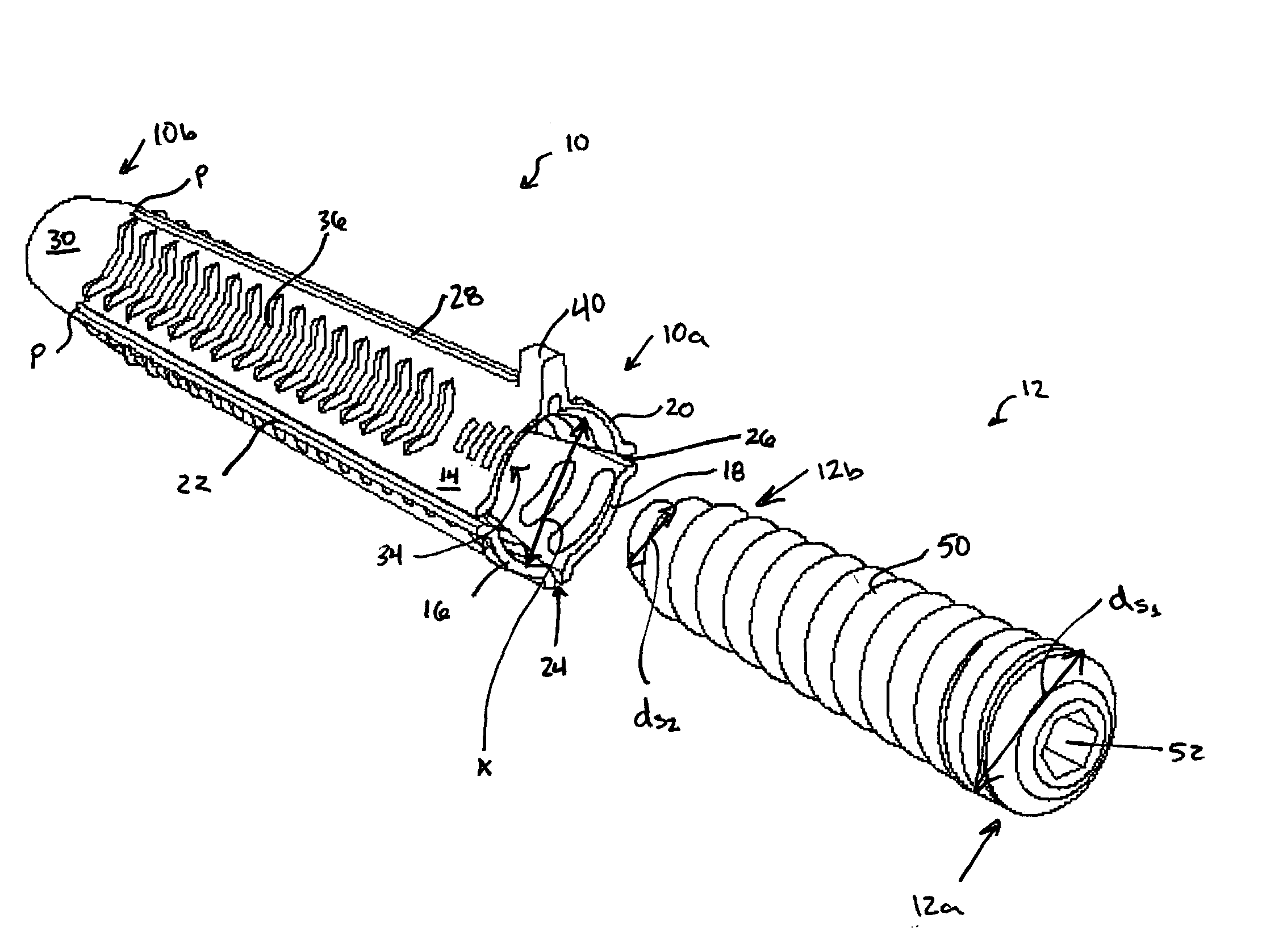
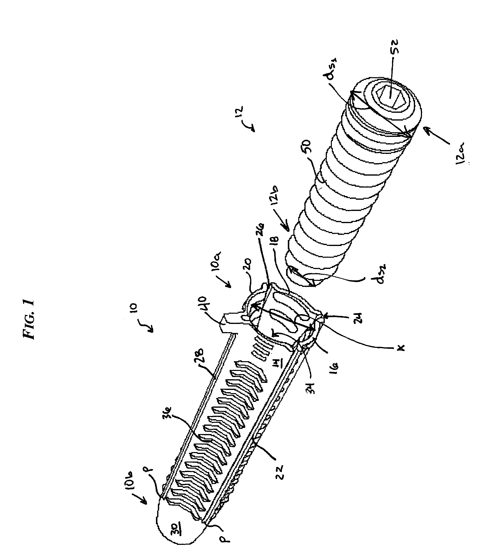
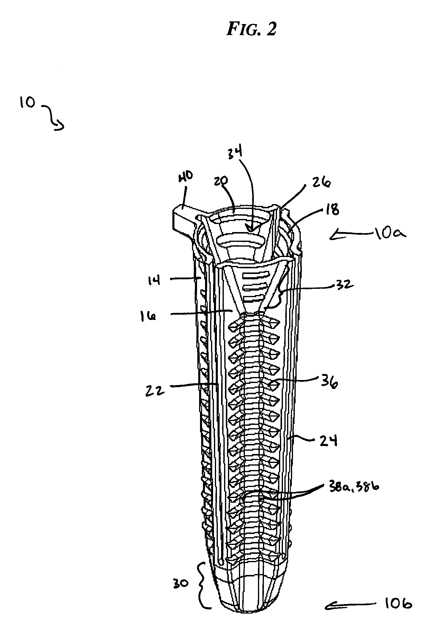
[0019]As shown in FIG. 1, the present invention generally provides a radially expandable sheath 10 for attaching a ligament graft to bone. In general, the expandable sheath has a substantially closed distal end with at least two sidewalls (FIG. 1 illustrates four sidewalls 14, 16, 18, 20) extending proximally therefrom and defining an inner lumen 34. Each sidewall 14, 16, 18, 20 can have a substantially concave outer surface adapted to seat a graft member, and each sidewall 14, 16, 18, 20 is at least partially separated by a longitudinally oriented slot 22, 24, 26, 28 that extends from a proximal end 10a along a substantial length of each sidewall 14, 16, 18, 20. The slots 22, 24, 26, 28 preferably terminate at a position just proximal to the distal end 10b of the sheath 10. The device can also optionally include a sheath expander 12 that is adapted to be disposed in the central lumen 34 of the radially expandable sheath 10 and that is configured to flex the sidewalls 14, 16, 18, 20...


PUM


Abstract

A radially expandable sheath is provided having a substantially closed distal end with at least two sidewalls extending proximally therefrom and defining a central lumen. Each sidewall can have a substantially concave outer surface adapted to seat a graft member, and each side wall is at least partially separated by a longitudinally oriented slot that extends from a proximal end along a substantial length of each sidewall. The slot preferably terminates at a position just proximal to the distal end. The device can also include a sheath expander that is adapted to be disposed in the central lumen of the radially expandable sheath and that is configured to flex the sidewalls to radially expand the sheath so as to fix a graft member within a bone tunnel.

Description

FIELD OF THE INVENTION[0001]The present invention relates to ligament fixation devices and methods, and more particularly to devices and methods for anchoring ligaments within a bone tunnel.BACKGROUND OF THE INVENTION[0002]Ligaments are tough bands of tissue which serve to connect the articular extremities of bones, or to support or retain organs in place within the body. Ligaments are typically composed of coarse bundles of dense white fibrous tissue which are disposed in a parallel or closely interlaced manner, with the fibrous tissue being pliant and flexible, but not significantly extensible.[0003]In many cases, ligaments are torn or ruptured as a result of accidents or overexertion. Accordingly, various procedures have been developed to repair or replace such damaged ligaments. For example, in the human knee, the anterior and posterior cruciate ligaments (i.e., the ACL and PCL) extend between the top end of the tibia and the bottom end of the femur. The ACL and PCL cooperate, t...

Claims


Application Information

Patent Timeline
IPC IPC(8): A61F2/08A61B17/56A61F2/28
CPCA61F2/0811A61F2002/0888A61F2002/0858A61F2002/0835
Inventor DONNELLY, LISA M.CAULDWELL, NATHAN S.
Owner DEPUY SYNTHES PROD INC
Why Eureka
Try Eureka