
Power supply arrangement for battery powered device

a battery-powered device and power supply technology, applied in the direction of ac-dc conversion, transmission, electric variable regulation, etc., can solve the problems of size problems, stability problems, magnetic interference, etc., and achieve the effect of optimizing the system efficiency

Active Publication Date: 2007-12-11
OTICON
View PDF11 Cites 11 Cited by
  • Summary
  • Abstract
  • Description
  • Claims
  • Application Information

AI Technical Summary

Benefits of technology

[0005]By performing the conversion in this manner there has been provided an opportunity for a more energy efficient conversion than hitherto known in connection with battery powered headworn communication devices. The conversion may be performed in a stable manner and a sufficient voltage can be maintained during the lifetime of the battery.
[0007]By the embodiment set forth in claim 2 the two systems are operated in parallel hereby enabling a simple implementation.
[0009]By balancing the fixed part voltage conversion and the variable part conversion, a possibility of optimising the efficiency of the system may be achieved. In a system comprising a switched capacitor part this is preferably done by setting the clock frequency of the switched capacitor part.

Problems solved by technology

This solution has a good efficiency but suffers from a variety of problems due to the presence of an inductor, which gives rise to magnetic interference, stability problems and in some cases size problems.
In principle, this would have a satisfactory function, however, for battery voltages below a certain voltage the output supply can no longer be guaranteed to be the desired.
Low battery voltage may occur gradually or instantaneously (sudden load changes) during lifetime of the battery.
A third possibility is to use linear regulators to provide a lower voltage than the battery voltage, however a drawback for such conversion is that the energy efficiency is poor.

Method used


Image

  • Power supply arrangement for battery powered device
  • Power supply arrangement for battery powered device
  • Power supply arrangement for battery powered device

Examples


Embodiment Construction

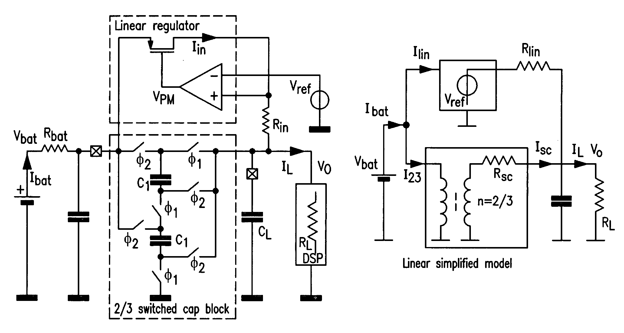
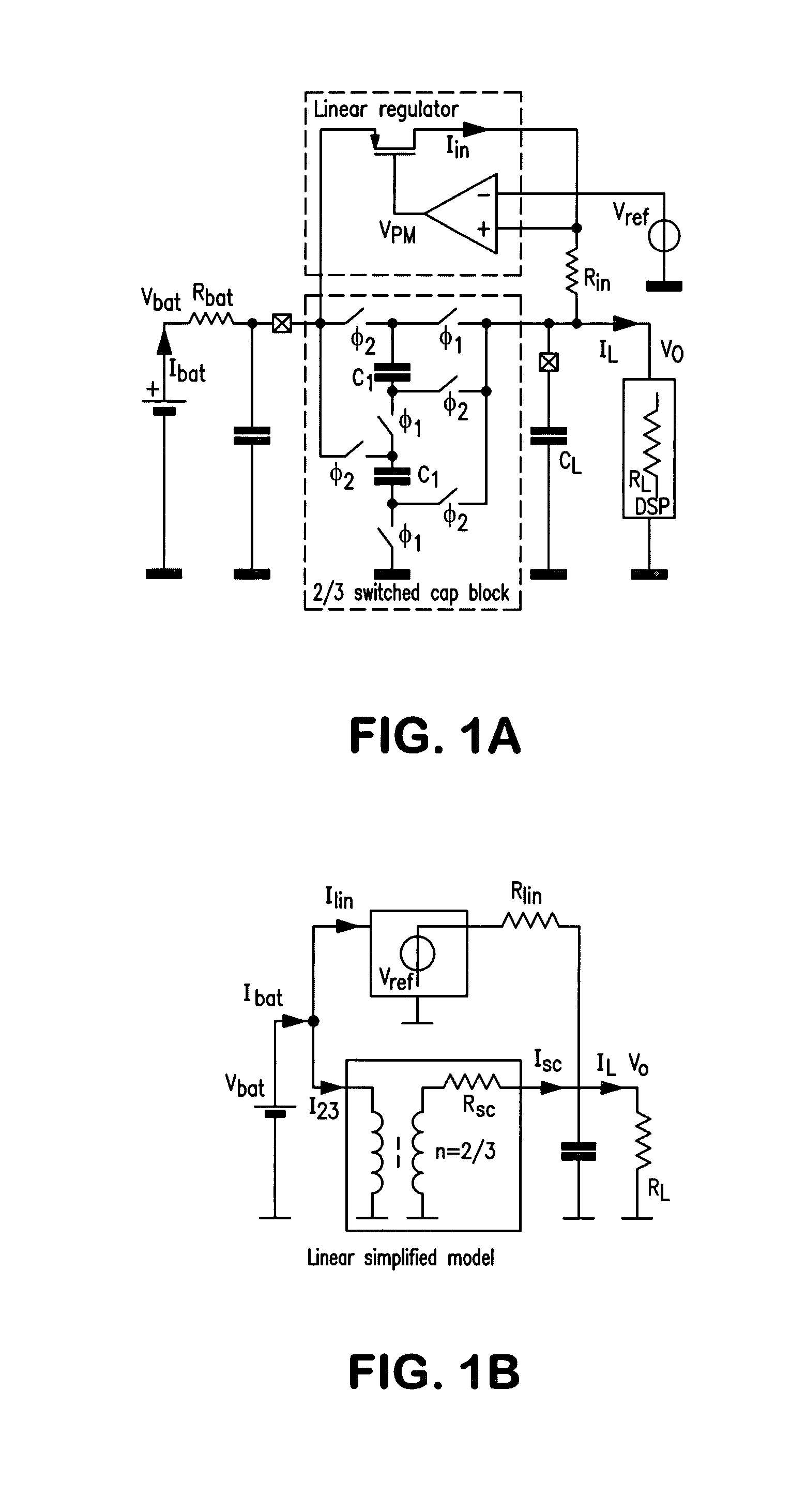
[0021]It should be appreciated that the system in principle can be adapted to any input and output voltages and still have the same advantages as in the specific example. The example shown is related to a battery powered headworn communication device, and more specifically to a hearing aid or a headset.

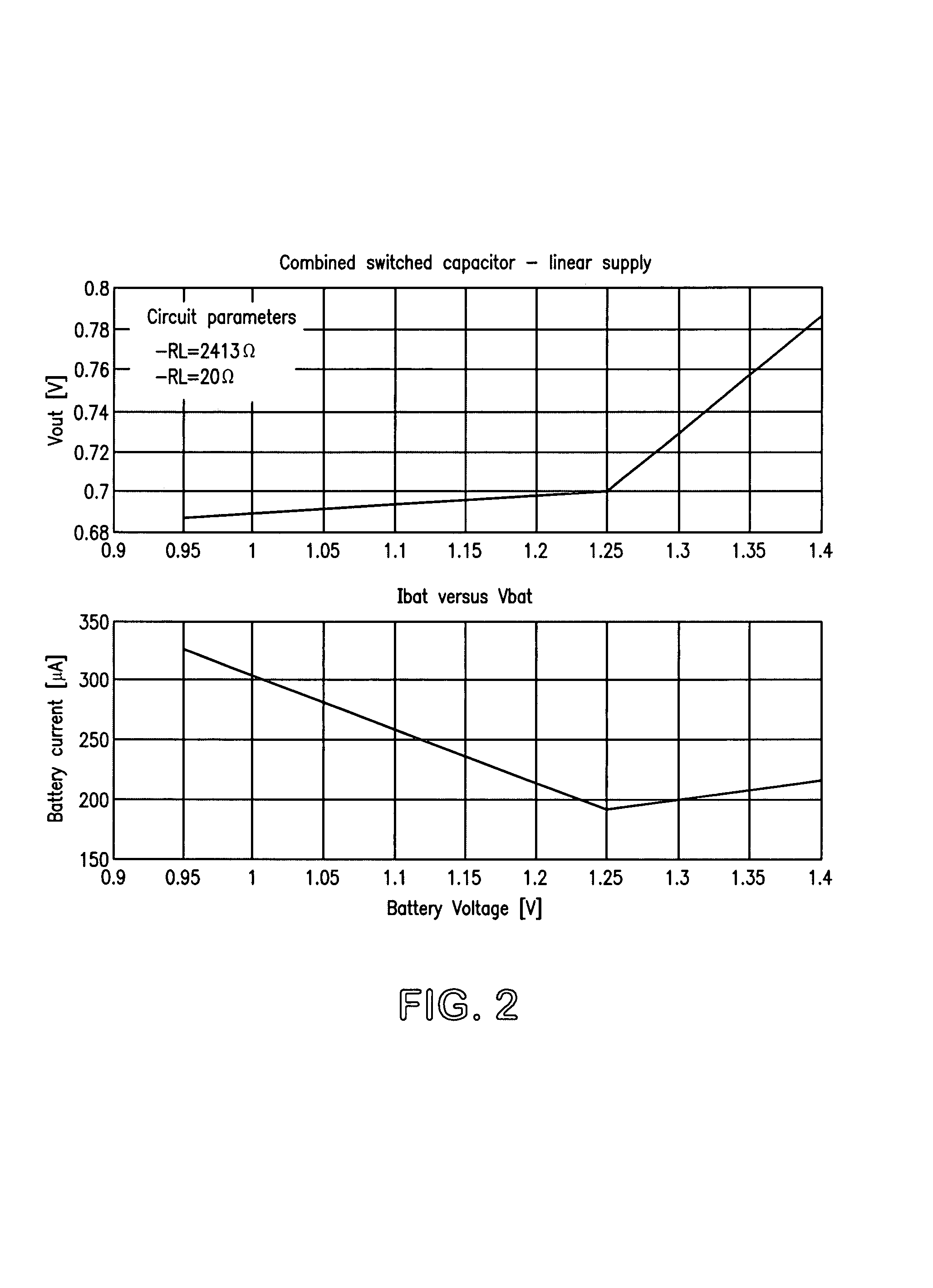
[0022]The SC step down converter provides a power efficient conversion of the battery voltage by a factor of e.g. ⅔while the linear regulator ensures operation of the digital supply at low battery voltages. This technique as explained in the following allows significant saving of battery current compared to a supply based on a pure linear regulator.

[0023]The (high) battery voltage should power efficiently be transformed to a pre-defined lower supply voltage, which can be provided by a SC step down converter. This SC-power converter can however not guarantee sufficient output voltage at a low battery supply. A combination of a linear and a switched capacitor supply is therefore propose...


PUM


Abstract

A battery powered headworn communication device and a method for conversion of a battery voltage in a battery powered headworn communication device, which includes providing a voltage reduction to a fixed part of the input voltage and providing a variable reduction that ensures that a minimum voltage is maintained. Preferably, the fixed part reduction and the variable reduction are performed in parallel and the fixed voltage conversion is a ⅔ conversion of the input voltage. A fixed voltage conversion and the variable conversion can be balanced according to the actual battery voltage.

Description

[0001]The invention relates to the area of power supply systems for use in connection with battery powered headworn communication devices. More specifically the invention relates to power supply systems where the battery voltage is higher than desired and therefore need to be reduced. Such battery-powered devices may be hearing aids, telephone headsets and other mobile devices.BACKGROUND OF THE INVENTION[0002]In connection with battery powered headworn communication devices it is previously known to use a switched mode power supply based on a class-D driver and an external LC-lowpass filter. This solution has a good efficiency but suffers from a variety of problems due to the presence of an inductor, which gives rise to magnetic interference, stability problems and in some cases size problems. Another idea is to use a switched capacitor step down converter, which in no-load condition would linearly transform the battery voltage to a fraction of it. In principle, this would have a sa...

Claims


Application Information

Patent Timeline
Patent Type & Authority Patents(United States)
IPC IPC(8): H02M3/06H02M3/07
CPCH02M3/07
Inventor KURATLI, CHRISTOPH
Owner OTICON
Learn More