Multipart oil wiping ring for pistons of internal combustion engines

a technology of internal combustion engine and oil wiping ring, which is applied in the direction of mechanical equipment, braking systems, transportation and packaging, etc., can solve the problems of high friction power during engine operation, high surface pressure against the working surface of steel lamellae, and worsen the degree of effectiveness of internal combustion engine, so as to improve the oil control effect and reduce the wear of the working surfa

Active Publication Date: 2007-12-11
MAHLE GMBH
View PDF23 Cites 8 Cited by
  • Summary
  • Abstract
  • Description
  • Claims
  • Application Information

AI Technical Summary

Benefits of technology

[0006]It is the task of the invention to indicate a multi-part oil control ring for a piston of an internal combustion engine, which has an improved oil control effect as compared with the known state of the art, at a reduced wear of the working surface.
[0009]By means of the working surface configuration according to the invention, and the arrangement of the lamellae relative to one another, a reduction in the friction power of the entire steel-band oil control ring is achieved, by means of a more advantageous hydrodynamic condition at one of the two lamellae, without any reduction in tangential force, whereby the oil-controlling function of the other lamella is maintained to its full extent, in this connection. The reduction in the friction power thereby results in an improvement of the degree of effectiveness of the engine, or the oil control behavior can be improved by means of an increase in the tangential force, with an unchanged friction power level.

Problems solved by technology

However, this results in a high surface pressure against the working surfaces of the steel lamellae, and therefore a high friction power during engine operation.
This friction power worsens the degree of effectiveness of the internal combustion engine and accordingly increases the fuel consumption.

Method used


Image

  • Multipart oil wiping ring for pistons of internal combustion engines
  • Multipart oil wiping ring for pistons of internal combustion engines

Examples


Embodiment Construction

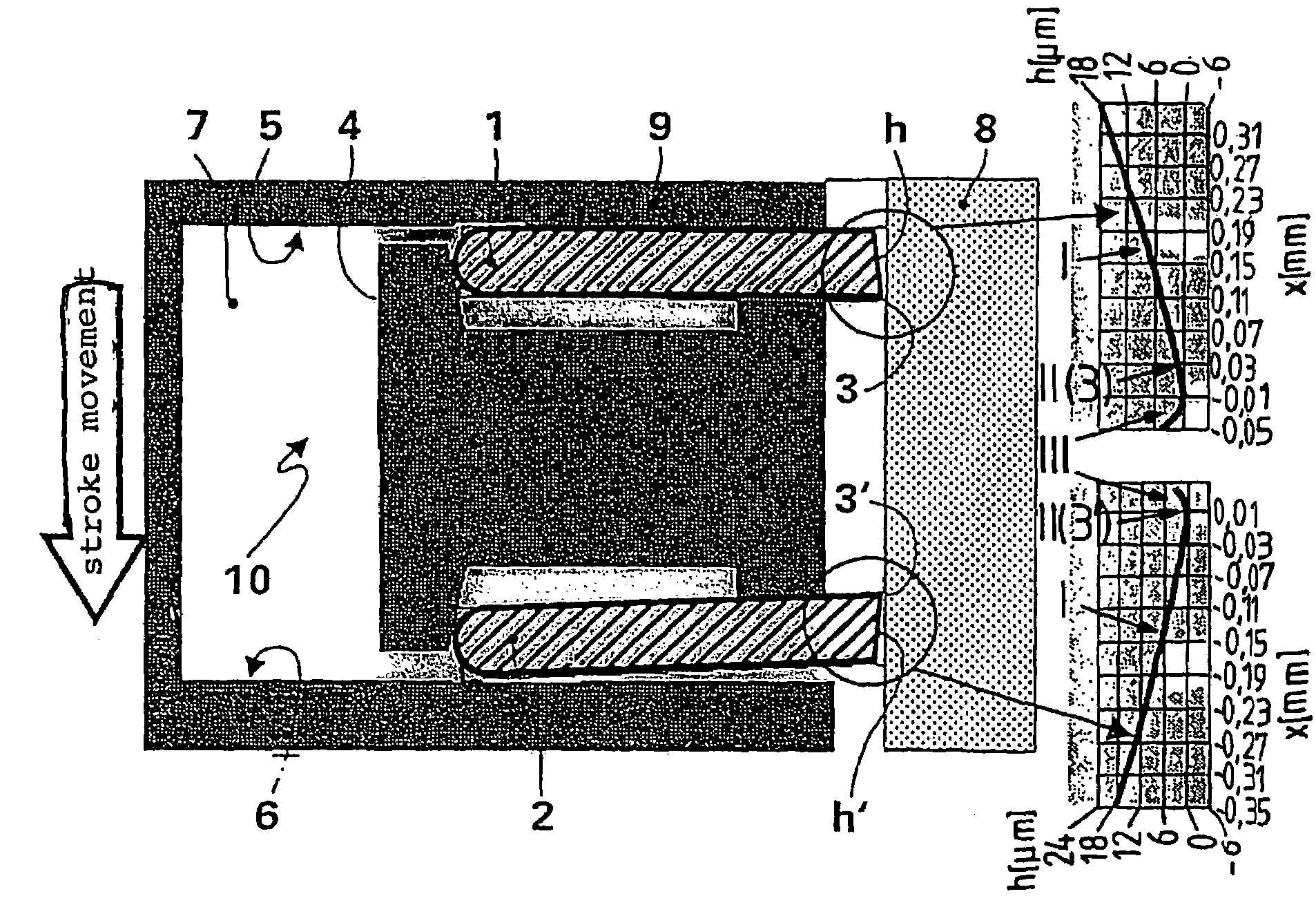
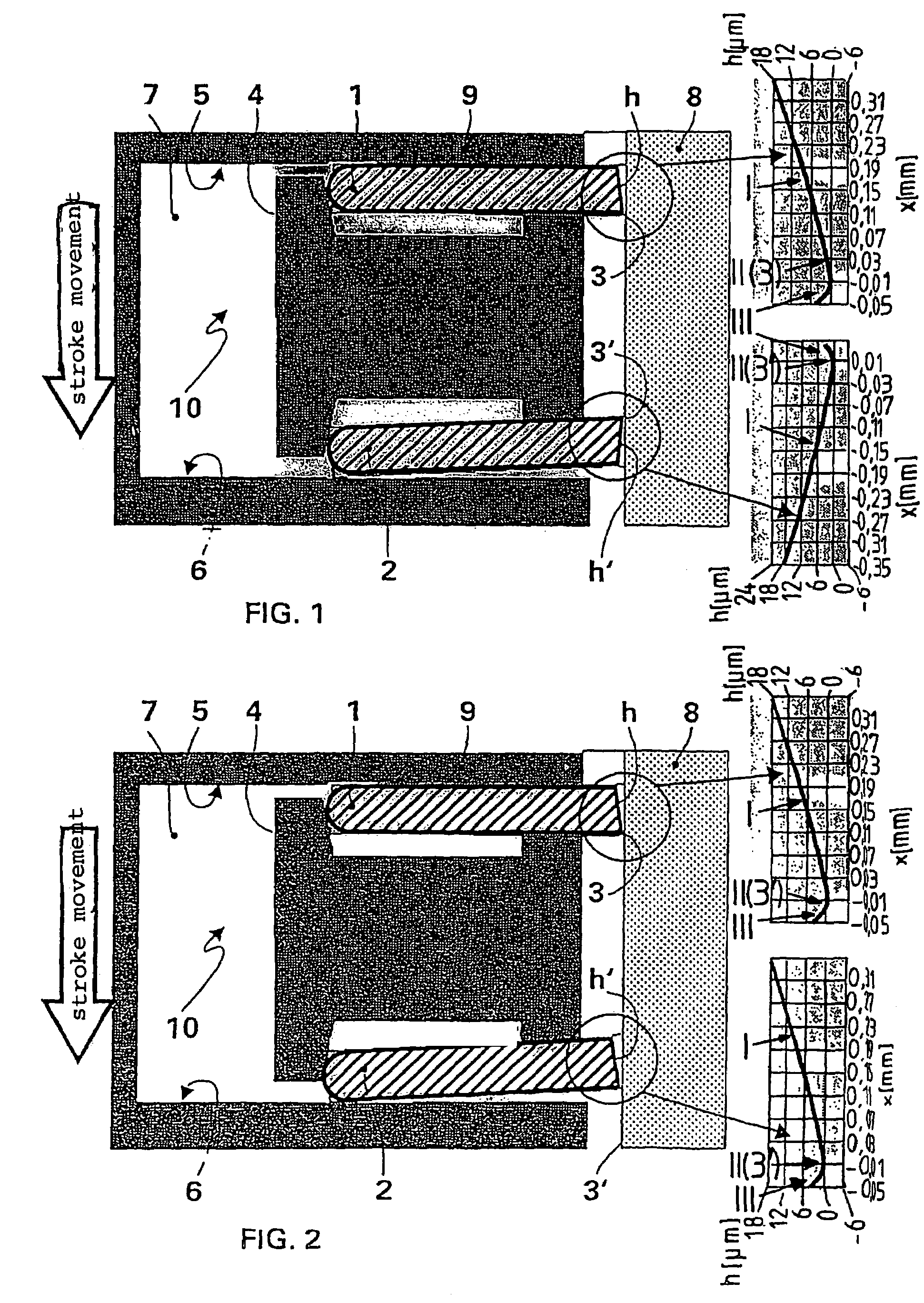
[0014]As is evident from FIG. 1, a multi-part oil control ring 10 consists of two steel-band lamellae 1 and 2 and a spreading spring 4, which presses the lamellae both axially against one of the walls 5 and 6 of the ring groove 7 in the piston, and radially against the cylinder wall 8. The ring groove wall 5 represents the piston crown side, and the ring groove wall 6 represents the side facing away from the piston crown. According to the invention, the lamella 1 has a barrel-shaped asymmetrically shaped working surface h with a vertex line 3 that extends over the circumference of the lamella, and the lamella 2 has a barrel-shaped asymmetrical working surface h′ with a vertex line 3′, whereby the vertex lines 3, 3′, in each instance, act as edges that stand in contact with the cylinder wall 8, for oil control. In a first exemplary embodiment according to FIG. 1, the lamellae 1 and 2 are disposed relative to one another, in their assembled state, in such a manner that their vertex li...


PUM


Abstract

A multipart oil wiping ring for pistons of internal combustion engines comprises two steel strip-type lamellae with parallel sides, the running surfaces of which are provided with a convexly asymmetric shape having a vertex line that extends across the circumference of the lamellae, and a bracing spring located between the lamellae. The bracing spring presses the lamellae in an axial direction against one respective side of an annular groove in the piston and in a radial direction against the cylinder wall.

Description

CROSS REFERENCE TO RELATED APPLICATIONS[0001]Applicant claims priority under 35 U.S.C. §119 of German Application No. 103 40 312.4 filed Sep. 2, 2003. Applicant also claims priority under 35 U.S.C. §365 of PCT / DE2004 / 001939 filed Sep. 1, 2004. The international application under PCT article 21(2) was not published in English.BACKGROUND OF THE INVENTION[0002]The invention relates to a multi-part oil control ring for pistons of internal combustion engines, having two lamellae consisting of steel strips that have parallel walls, the working surfaces of which have a barrel-shaped asymmetrical shape, in each instance, having a vertex line that extends over the circumference of the lamellae, as well as having a spreading spring disposed between the lamellae, which presses the lamellae both axially against one of the walls of a ring groove in the piston, in each instance, and radially against the cylinder wall.[0003]In order to prevent too much motor oil from getting into the combustion ch...

Claims


Application Information

Patent Timeline
IPC IPC(8): F16J9/20F16J9/06
CPCF16J9/206F16J9/066F16J9/20F16J9/06F16J9/00
Inventor FIEDLER, ROLF-GERHARD
Owner MAHLE GMBH
Why Eureka
Try Eureka