Multi-stage fluid power turbine for a fire extinguisher

a technology of fluid power turbine and fire extinguisher, which is applied in the direction of machines/engines, mechanical equipment, lighting and heating apparatus, etc., can solve the problems of large outdoor grass and hillside fires, large acreage burned at alarming rates, and increasing damage or destruction of homes and private property

Inactive Publication Date: 2007-12-11
MOFLIHI SAEED M
View PDF16 Cites 17 Cited by
  • Summary
  • Abstract
  • Description
  • Claims
  • Application Information

AI Technical Summary

Benefits of technology

[0008]Briefly, and in general terms, a multi-stage fluid power turbine is disclosed having particular application as a fire extinguisher for fighting outdoor fires. The fire extinguisher is sized to be ideally mounted atop and carried by a fire engine (e.g., a tanker or a pumper) to the scene of the fire. The fire extinguisher includes an impeller, a propeller and a fan that are axially aligned with one another and rotate within a turbine housing so that a high humidity air and water spray can be blown at high velocity and pressure towards the fire to be extinguished.

Problems solved by technology

Large outdoor grass and hillside fires have become a common problem, particularly in areas of California, Texas and Oklahoma.
Not only has vast acreage been burned at alarming rates, but homes and private property have been increasingly subjected to damage or destruction.
The same problems exist with large structural fires as well as vehicle and airplane fires.
The process of removing and readying a fire hose for use wastes valuable time.
Moreover, fire hoses are often strewn about, which can pose a safety hazard for fire fighters who must move quickly around the scene without always being able to watch where they step.

Method used


Image

  • Multi-stage fluid power turbine for a fire extinguisher
  • Multi-stage fluid power turbine for a fire extinguisher
  • Multi-stage fluid power turbine for a fire extinguisher

Examples


Embodiment Construction

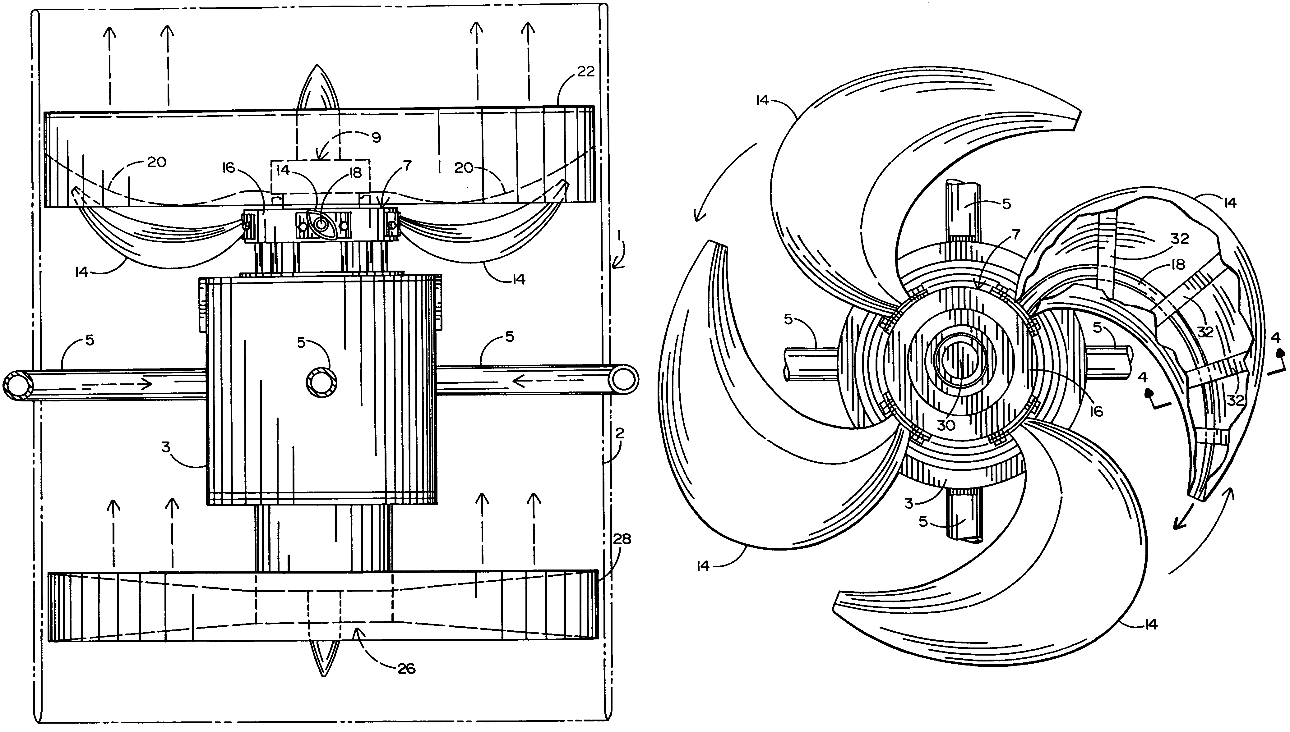
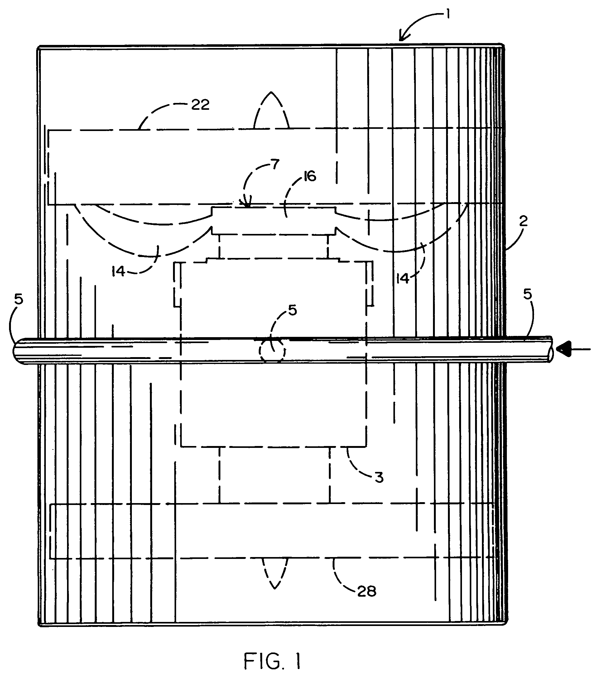
[0018]Referring initially for FIGS. 1 and 2 of the drawings, there is shown a fire extinguisher 1 according to a preferred embodiment that is adapted to generate a high humidity spray including a mixture of air and water to be blown at high velocity and high pressure towards an outdoor fire such as that which has been known to consume large amounts of acreage. However, the fire extinguisher 1 of this invention may also be used to fight other fires such as those which have known to be engulf a motor vehicle, aircraft or large structure. To this end, it is contemplated that the fire extinguisher 1 will be relatively compact (i.e., approximately 3 meters wide) so as to be ideally mounted atop and carried by a fire engine (e.g., a tanker or a pumper) whereby the fire extinguisher 1 will have ready access to the water transported thereby. However, the fire extinguisher herein disclosed may be transported to a fire by any other suitable means so long as a source of municipal or portable w...


PUM


Abstract

A multi-stage fluid power turbine having application as a fire extinguisher to be ideally carried by a fire truck (e.g., a tanker or a pumper) so as to fight outdoor fires. An impeller and a propeller are located at one end of the fire extinguisher, and a fan is located at the opposite end. The propeller and the fan are mounted on a common inner shaft so as to rotate in a first direction. The impeller is mounted on a hollow outer shaft or tube that surrounds the inner shaft. The impeller includes a plurality of curved blades, each of which having a fluid duct running therethrough. Water under pressure being supplied from a source to the impeller blades is ejected from the fluid ducts thereof and thrust against the blades of the propeller, whereby to impart a rotational force to the propeller and a corresponding rotational force to the fan. The water ejected from the curved impeller blades causes the impeller to rotate in an opposite direction. Accordingly, the propeller breaks up the supply of water ejected from the impeller blades so that a high humidity air and water spray is blown by the fan at high velocity and pressure towards the fire to be extinguished.

Description

BACKGROUND OF THE INVENTION[0001]1. Field of the Invention[0002]This invention relates to a fire extinguisher that is sized to be ideally mounted atop and carried by a fire truck (e.g., a tanker or a pumper) which transports a water supply to be used for fighting outdoor fires. The fire extinguisher herein disclosed includes an impeller, a propeller and a fan that are axially aligned with one another to form a multi-stage fluid power turbine so that a high humidity air and water spray can be blown at high velocity and pressure towards a fire to be extinguished.[0003]2. Background Art[0004]Large outdoor grass and hillside fires have become a common problem, particularly in areas of California, Texas and Oklahoma. Not only has vast acreage been burned at alarming rates, but homes and private property have been increasingly subjected to damage or destruction. Because such outdoor fires typically burn at high temperatures and are often wind driven, it is important that fire fighters hav...

Claims


Application Information

Patent Timeline
Patent Type & Authority Patents(United States)
IPC IPC(8): A62C31/00
CPCA62C3/0207A62C99/0072F04D25/04F04D13/04B05B3/022
Inventor MOFLIHI, SAEED M.
Owner MOFLIHI SAEED M
Why Eureka
Try Eureka