Eureka AIR delivers breakthrough ideas for toughest innovation challenges, trusted by R&D personnel around the world.

Loop fabric

a loop fabric and loop technology, applied in haberdashery, synthetic resin layered products, printing, etc., can solve the problems of dimensional instability, high cost, and general specialized and costly backings, and achieve low cost, high strength, and increase the availability of fibers.

Active Publication Date: 2007-12-04
3M INNOVATIVE PROPERTIES CO
View PDF22 Cites 61 Cited by
  • Summary
  • Abstract
  • Description
  • Claims
  • Application Information

AI Technical Summary

Benefits of technology

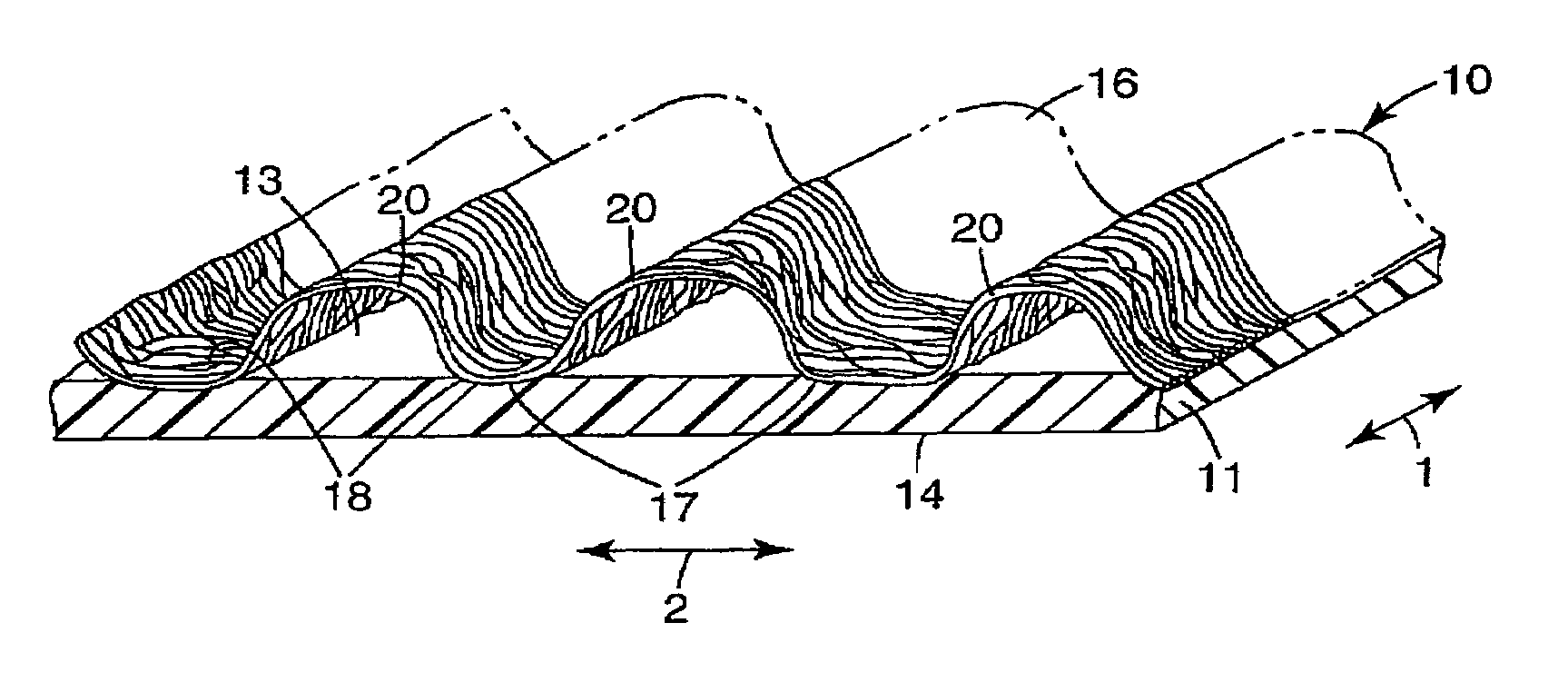
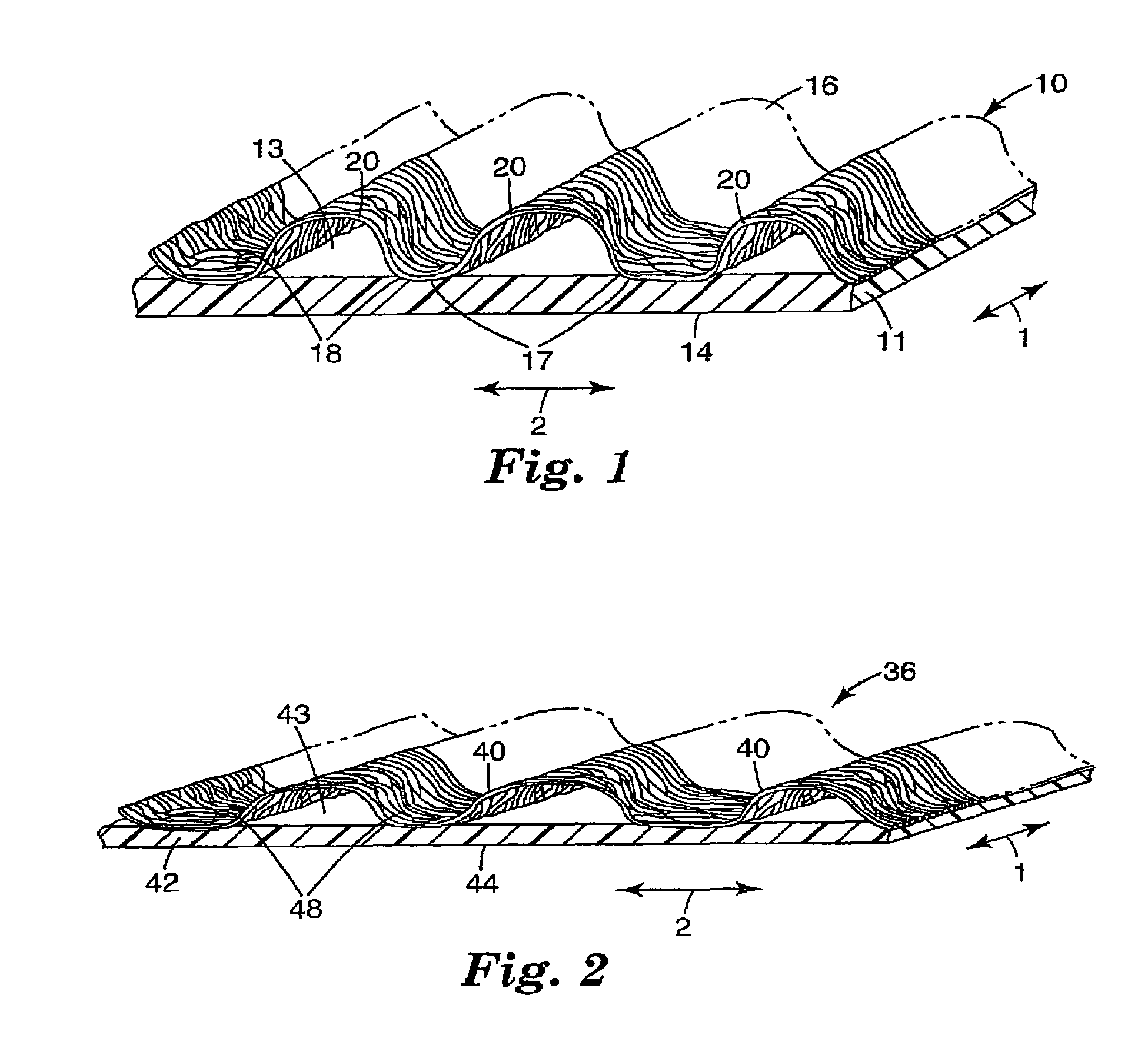
[0004]The present invention provides improved inelastic, dimensionally stable, high strength loop composite comprising an oriented inelastic film extending in at least a first direction and one or more sheets of flexible nonwoven material intermittently bonded along at least one surface portion of the oriented inelastic film. Preferably, the loop has regularly spaced bond portions between the nonwoven material and the oriented film. These intermittent bond anchor portions are separated by unbonded portions where the film and nonwoven material face each other, but are not bonded. These loop composites provide unique advantages as a low cost, flexible or soft, dimensionally stable, high performing loop which is relatively simple to manufacture.
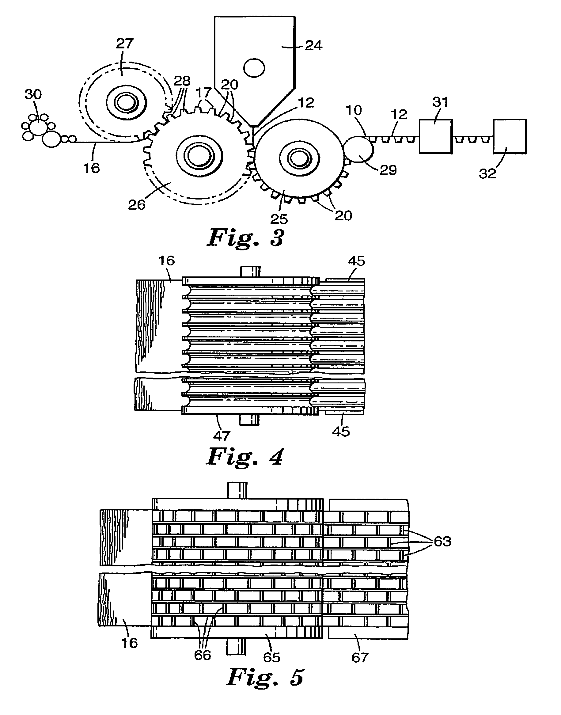
[0005]According to the present invention there is also provided a method for forming a loop fabric sheet which comprises (1) providing a first sheet of flexible nonwoven material (e.g., nonwoven web of natural and / or polymeric fibers, and / or yams); (2) forming the first sheet of flexible nonwoven material to have arcuate portions projecting in the same direction from spaced anchor portions of the first sheet of flexible nonwoven material; (3) extruding a sheet of thermoplastic material that is inelastic (e.g., polyesters, polyolefins, nylons, polystyrenes) onto the first sheet of flexible loop material; (4) providing the film thermoplastic while still molten to at least the spaced anchor portions of the first sheet of flexible nonwoven material to bond the extruded thermoplastic film sheet to the nonwoven material at bond sites or the anchor portions; and (5) orienting the extrusion bonded nonwoven fabric sheet composite in at least the longitudinal direction of the sheet thereby orienting the sheet and reducing the height of arcuate portions of the nonwoven. By this method there is provided a novel sheet-like nonwoven loop composite comprising a flexible nonwoven intermittently bonded to a thin, high strength oriented film.

Problems solved by technology

However, the backings are generally specialized and costly, dimensionally unstable, or thick.

Method used


Image

  • Loop fabric
  • Loop fabric
  • Loop fabric

Examples


example 1

[0035]The nonwoven loop composite C1 was biaxially oriented using a KARO IV pantograph stretcher (Bruckner Gmbh, Siegfred, Germany). A 115 mm by 115 mm sample was cut from the web of the composite and mounted in the stretcher. The sample was heated for 60 seconds at 140° C. and then stretched at a rate of 100% / sec to a final dimension of approximately 150 mm by 150 mm resulting in a biaxial orientation of 1.5 to 1 in both the machine and cross directions of the sample. The sample was removed from the stretcher and tested for tensile strength and peel and shear properties.

example 2

[0037]The nonwoven loop composite C2 was oriented in the cross direction using a KARO IV pantograph stretcher. A 115 mm by 115 mm sample was cut from the web of the composite and mounted in the stretcher. The sample was heated for 60 seconds at 140° C. and then stretched in the cross direction at a rate of 100% / sec to a final dimension of approximately 100 mm by 250 mm resulting in a cross direction orientation of 2.5 to 1. The sample was removed from the stretcher and tested for tensile strength and peel and shear properties.

example 3

[0038]The nonwoven loop composite C2 was oriented in the machine direction using a KARO IV pantograph stretcher. A 115 mm by 115 mm sample was cut from the web of the composite and mounted in the stretcher. The sample was heated for 60 seconds at 140° C. and then stretched in the machine direction at a rate of 100% / sec to a final dimension of approximately 250 mm by 100 mm resulting in a machine direction orientation of 2.5 to 1. The sample was removed from the stretcher and tested for tensile strength and peel and shear properties.


PUM

PropertyMeasurementUnit
heightaaaaaaaaaa
diameteraaaaaaaaaa
heightaaaaaaaaaa

Abstract

This invention relates to a low cost loop material for a hook and loop fastener having at least one sheet of flexible nonwoven material intermittently bonded to inelastic oriented film. The invention further relates to methods for producing these loops.

Description

BACKGROUND AND SUMMARY[0001]The present invention relates to a low cost loop material for a hook and loop fastener having at least one sheet of flexible nonwoven material intermittently bonded to inelastic oriented film. The invention further relates to methods for producing these loops.[0002]Loop fabrics formed by lamination of nonwovens to film are known from, for example, U.S. Pat. No. 5,032,122 which is formed by providing a backing of orientable material in its dimensionally unstable state; positioning a plurality of filaments on the backing; securing the filaments to the backing at spaced, fixed regions along each of the filaments, the fixed regions defining between each pair an unsecured catching region; and causing the orientable material to be transformed along its path of response to its dimensionally stable state thereby shirring the filaments at the catching regions to form fibrous elements projecting from the backing between the fixed regions. U.S. Pat. No. 5,547,531 de...

Claims


Application Information

Patent Timeline
Patent Type & Authority Patents(United States)
IPC IPC(8): B32B5/00B29C47/00B32B27/12B32B3/06B32B3/28D05C15/00A44B18/00B32B37/15D04H1/558D04H1/559D04H13/00
CPCA44B18/0011B32B27/12B32B38/00D04H13/002B32B37/153B32B2305/20Y10T156/101Y10T428/24802Y10T428/24612Y10T428/2457Y10T428/24008Y10T428/2481Y10T428/23979Y10T442/674B32B3/28A44B18/00B32B27/302B32B2398/20B32B27/34B32B27/32B32B27/36B32B38/0012B32B2307/54
Inventor SETH, JAYSHREEBECKER, DENNIS L.
Owner 3M INNOVATIVE PROPERTIES CO
Why Eureka
Eureka Blog
Learn More